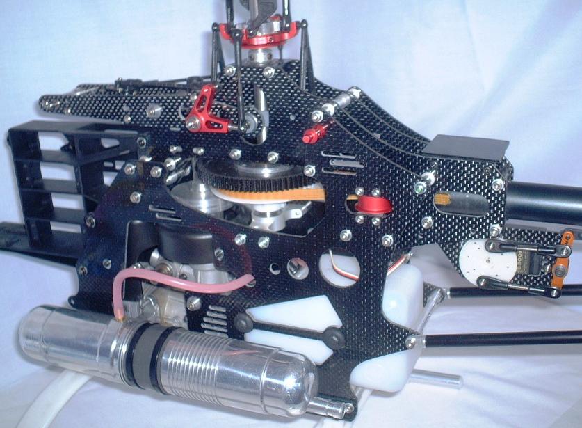
Where Did The Boom Supports Go?
For decades, twin diagonal tail boom struts were an essential fixture on collective-pitch RC helicopters. Anchored near the base of the main frame and clamping onto the midpoint of the aluminum tail tube, these supports formed a rigid triangle designed to prevent tail flex, high-frequency resonance, and boom strikes. Today, a look across the flight line at events like IRCHA reveals a clear shift: tail boom supports are rapidly disappearing across all size classes. This article examines the structural physics, key manufacturer innovations—including landmark contributions from Oxy Helicopter (Lynx Heli)—and the engineering required to run strutless tail booms.
1. The Evolution: Who Started It, and Who Perfected It?
The move away from legacy 20mm–22mm thin-wall aluminum booms with diagonal carbon struts was driven by a pursuit of lower parts counts, cleaner aerodynamics, faster crash repairs, and modern aesthetic styling.
The Big-Model Originators: SAB Goblin & Mikado Logo
- SAB Heli Division (Goblin Series): SAB popularized the supportless boom movement in 2011–2012 with the original Goblin 700. SAB abandoned traditional round tubes in favor of a broad, molded carbon-fiber monocoque tail boom that bolted directly to a heavy-duty aluminum frame clamp.
- Mikado (Logo 700 / 800 XXtreme): Around the same era, Mikado introduced oversized 30mm and 35mm thick-wall round aluminum booms on their large-scale airframes, proving that increasing tube diameter could eliminate the need for external struts.
The Mid-Size & Micro Pioneers: Oxy Helicopter (Lynx Heli Innovations)
While SAB and Mikado proved the concept on large 700/800-class airframes, Luca Invernizzi and Oxy Helicopter (a division of Lynx Heli Innovations) played a key role in bringing supportless tail architecture to smaller, high-RPM airframes:
- Ovalized & Oversized Shaped Booms: Oxy introduced custom non-circular boom profiles—such as the Oxy 4 Max's supportless oval carbon boom—designed specifically to maximize vertical bending resistance while minimizing lateral aerodynamic drag in extreme 3D flight.
- Rigid Triple-Bearing Frame Integration: Oxy engineered ultra-rigid carbon/aluminum frame blocks with deep clamping channels. This design isolated motor torque and allowed small-to-midsize helis (like the Oxy 4, Oxy 4 Max, and Oxy 5) to handle over 3,000 RPM head speeds without flexing or needing boom struts.
- Field Serviceability Focus: Oxy designed their supportless tail booms around a single-bolt or quick-release clamping mechanism. This allowed pilots to loosen one clamp, slide the boom forward to slacken the belt, and remove the tail assembly for transport or crash repair without unbolting strut hardware.
The Broader Industry Follow-Through
- XLPower (Specter Series): XLPower popularized large-diameter (32mm+) ultra-light carbon round tubes clamped inside massive aluminum frame blocks across their 700 and 550 platforms.
- SAB Goblin RAW Series: SAB shifted from full-monocoque shapes to thick-wall, large-diameter matte carbon round tubes with integrated frame block clamping.
- ALIGN (T-Rex X-Series & Dominator Lines): Align embraced teardrop-shaped and thick-wall carbon booms on their high-torque X-series airframes to replace classic strutted assemblies.
2. The Physics: How Engineers Compensate for Missing Struts
To understand how modern airframes eliminate boom supports, we look at the mechanical forces acting on a tail assembly during extreme 3D maneuvers (such as hard wall-stops, hurricane turns, and tail-first pitch pumps):
Second Moment of Area (Bending Resistance, $I$) = $\frac{\pi}{64} \times (D_{outer}^4 - D_{inner}^4)$
Torsional Constant (Twist Resistance, $J$) = $\frac{\pi}{32} \times (D_{outer}^4 - D_{inner}^4)$
Key Engineering Takeaway: Rigidity scales with the fourth power of the diameter ($D^4$). Increasing boom diameter yields exponentially greater strength than adding wall thickness or external struts.
By leveraging this geometric relationship, engineers compensate for the lack of diagonal supports using four primary design strategies:
| Design Strategy | Legacy Strutted Design | Modern Supportless Design | Structural Advantage |
|---|---|---|---|
| Boom Geometry | 20mm – 22mm Round Tube | 30mm – 38mm Round or Ovalized Carbon | Bending stiffness increases by over 300% due to $D^4$ geometric scaling factor. Oval shapes (like Oxy 4 Max) add extra vertical rigidity. |
| Material & Weave | Extruded Thin Aluminum (0.8mm) or 3K Roll-Wrapped Carbon | Multi-axial Cross-Ply Carbon Fiber (0/45/90 degree layups) | Resists both vertical bending loads and rotational torque loads exerted by tail rotor collective. |
| Frame Clamping Block | Short aluminum pinch block (20mm length) | Deep dual-plate or interlocked aluminum socket (50mm–80mm depth) | Spreads bending moments over a larger frame surface area, preventing stress concentration fractures. |
| Rudder Servo Placement | Mounted mid-boom on external plastic brackets | Integrated inside the main carbon frame plates or inside the tail case | Removes weight from the middle of the cantilever beam, raising the natural resonant frequency of the tail. |
3. Discussions Across Forums & Community Newsboards
The shift away from tail supports remains a lively topic across forums like Helifreak, RC Groups, and Facebook builder groups. Field discussions highlight several clear tradeoffs:
The Advantages Celebrated by Pilots
- Simplified Crash Repairs & Transportation: In a crash, diagonal supports often bend, snap, or punch holes through canopy gelcoats. Supportless booms (especially on Oxy and SAB airframes) loosen via one or two frame bolts and slide straight out, making transport and repair significantly easier.
- Vibration Isolation & FBL Performance: Thin, strutted tail booms are prone to sympathetic harmonic vibrations—where the struts act like guitar strings, feeding micro-vibrations back into flybarless gyros. Thick supportless carbon booms damp high-frequency motor vibrations much more effectively.
- Aerodynamic Efficiency: Removing two drag-inducing support rods and their associated mounting clamps cleans up airflow from the main rotor downwash, yielding cleaner tail tracking in fast forward flight.
The Criticisms & Skepticism
- Frame Stress Concentration: Skeptics point out that while a supportless boom doesn't flex, the bending moment is transferred directly into the main carbon side-frames. In severe crashes, this can crack main chassis plates that might have otherwise survived on a strutted heli.
- Cost of Replacement Parts: A standard 22mm aluminum thin-wall boom costs $8 to $12, whereas a large-diameter 34mm multi-axial carbon tube or shaped oval boom costs $25 to $60.
4. Retrofitting Older Models: Can You Strip Boom Supports from Legacy Helis?
A frequent question among pilots maintaining classic airframes (like an older T-Rex 600/700, Blade 550X, or Synergy N9) is whether they can simply remove their diagonal tail supports to achieve a modern, clean look.
Removing tail supports from a helicopter designed for them is extremely dangerous. Standard legacy booms (typically 20mm to 22mm diameter with 0.8mm wall thickness) do not possess the structural section modulus required to support cyclic and tail rotor loads as a pure cantilever beam.
What Happens If You Remove Struts from an Older Heli?
- Low-Frequency Boom Flex & Tail Wobble: Under heavy collective pitch changes, the thin boom will flex vertically and laterally, causing severe gyro oscillation and tail hunting.
- Boom Strikes: During rapid elevator reversals or hard autorotation landings, main rotor blade deflection can cause the main blades to strike the flexing tail boom, resulting in catastrophic airframe destruction.
- Fatigue Failure at the Clamp: Because legacy frame blocks are short (often under 25mm of clamp engagement), the concentrated bending moment will quickly crack the thin aluminum boom or fracture the side frames right at the pinch bolts.
How to Safely Convert / Retrofit an Older Airframe
If you want to convert a legacy strutted helicopter into a supportless design, you must perform a complete structural upgrade of the tail assembly:
- Step 1: Upgrade to a Thick-Wall Carbon Boom: Replace the stock thin aluminum or thin 3K carbon tube with a custom thick-wall (1.5mm to 2.0mm wall thickness) pultruded or roll-wrapped carbon fiber tube.
- Step 2: Extend the Frame Mounting Socket: Fabricate or install an extended aluminum frame block or sleeve that supports at least 60mm–80mm of the front end of the boom inside the chassis.
- Step 3: Relocate the Tail Servo: Move the rudder servo off the tail boom and mount it inside the main frames, using a direct carbon pushrod guided inside or closely along the boom.
- Step 4: Grounding & Static Safety: Carbon-to-carbon friction in supportless clamps can generate static electricity on belt-drive systems. Ensure an internal copper grounding wire connects the tail case directly to the engine mount or motor plate.
5. Summary Verdict
The transition away from tail boom supports represents a major leap in composite engineering and structural design. Pioneers like SAB and Mikado proved the concept on large machines, while innovators like **Oxy Helicopter (Lynx Heli)** refined ovalized carbon geometry to bring strutless designs to smaller, high-performance airframes. While modern supportless helicopters are engineered for these loads from the ground up, older legacy airframes should always retain their diagonal supports unless undergoing a complete structural boom and clamp retrofit.