The Consequences of Incorrect Rotor Head Geometry
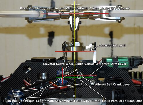
Imagine what the proper RC helicopter setup for the main rotor is like: The special point - the neutral point is where the servo horns are level (usually horizontal) and moving up the stack to the swashplate which then needs to be level on both the X and Y axis. Then continuing up, we have the flybarless driver arms which need be level or horizontal and then finally the blade pitch arms/grips at which point the blades are at 0 degrees pitch.
Also, refer to the picture for reference.
You agree, right?
Obviously you can achieve 0 degrees pitch even if the swashplate were too high or low by way of compensating via the length of the linkages right? This is what I see a lot of my students doing wrong. Here is a technical explanation of the consequences would be if they set it up improperly:
Yes, exactly. Absolute agreement on the mechanics. Starting from the bottom at the neutral/mid-stick point with horizontal servo horns, moving up to a perfectly level swashplate on both axes, leveling the flybarless driver arms, and finally achieving true 0 degrees pitch at the blade grips is the textbook standard for a clean mechanical setup.
As you noted, students often take a shortcut: they leave the swashplate sitting too high or too low at mid-stick and try to force 0 degrees pitch at the blades simply by lengthening or shortening the linkage rods.
Setting up the head with a mispositioned swashplate—rather than establishing proper geometry from the servos up—creates several severe technical and aerodynamic issues:
1. Cyclic Pitch Asymmetry (Differential Cyclic Response)
- The Problem: Servo arms operate through a rotational arc, whereas a swashplate and its linkages are designed to translate that motion linearly along the main shaft.
- The Interaction: Servo geometry is optimized when the arms are horizontal (at 90 degrees to the pushrods) at mid-stick. At this position, equal angular movement of the servo yields symmetrical linear travel up and down. If the swashplate is artificially placed too high or too low, the operating angle of the servo horn shifts away from that 90-degree sweet spot.
- The Result: As you roll or pitch the helicopter, the upward throw will differ from the downward throw (e.g., more right roll than left roll). This causes an asymmetrical feel in flight, making precision maneuvers difficult and forcing the flybarless (FBL) unit to constantly fight uneven mechanical limits.
2. Geometry Binding and Limited Pitch Travel Range
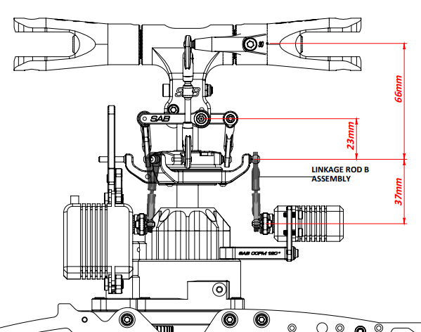
- The Problem: Every helicopter head is geometrically engineered around specific nominal linkage lengths and operating heights (such as the measurements illustrated in the diagram).
- The Interaction: Compensating for an incorrectly positioned swashplate by drastically altering link lengths forces pushrods outside of their designed angular operating range.
- The Result: You severely restrict your overall collective pitch range. If the swashplate is slammed too low to compensate with longer links, you risk running out of downward swash travel before hitting your negative pitch target, while risking mechanical binding at maximum positive pitch where ball links and turnbuckles can hit their physical angular limits or collide with the swashplate anti-rotation guide.
3. Progressive Pushrod Binding and Ball-Link Stress
- The Problem: Ball links are designed to pivot smoothly within a specific cone of movement.
- The Interaction: When pushrods are screwed abnormally long or short to make up for a misplaced swashplate, they sit at unnatural static angles relative to the balls on the mixing arms or swashplate.
- The Result: This increases friction, induces premature wear on the plastic links and brass balls, and can cause the links to snap under high aerodynamic loads. Worse, as the swashplate tilts through its full range of motion, these misaligned links will reach their binding threshold much sooner, stalling the servos or causing micro-stutters that degrade the FBL unit's stabilization loop.
4. FBL Unit Calibration and PID Confusion
- The Problem: Modern FBL units (like Rotorflight or similar systems) rely on the assumption that the mechanical setup mimics the digital geometry profile.
- The Interaction: If the baseline mechanical mid-point is skewed, the FBL unit's internal calibration for collective pitch limits and cyclic throws becomes skewed. While electronic sub-trims and limits can mask some of these errors, the software has to work harder to linearize the response curve.
- The Result: You end up with uneven resolution across your collective stick range, where the center stick might feel sluggish or hyper-sensitive depending on whether the swashplate error was high or low.
5. Conclusion
- Unequal feel when deflecting between left and right aileron.