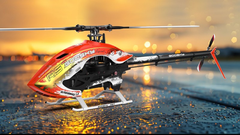
Goosky RS7 Ultra Technical Dossier
1. Overview
The GOOSKY RS7 Ultra is a 700-class electric radio-control helicopter developed around high-performance 3D flight. It uses a conventional flybarless collective-pitch architecture with a belt-driven tail, a large-diameter main rotor, a compact carbon/composite frame structure, and a 12S-class electric power system.
GOOSKY positions the RS7 Ultra as a competition-oriented machine, emphasizing high control authority, rapid tail response, structural durability, vibration isolation, aerodynamic efficiency and an optimized center-of-gravity layout.
The technical information in this document combines the supplied RS7 Ultra product information with specifications and mechanical details extracted from the RS7 Ultra instruction manual, together with clearly identified real-world owner/build observations.
2. Contents
- Core specifications
- Airframe dimensions
- Main rotor system
- Main drivetrain
- Tail-drive system
- Power system
- Battery system
- Structural design
- Rotor head and swashplate
- Bearing and shaft information
- Servo installation
- FBL / gyro installation
- Canopy and aerodynamics
- Landing gear
- Headspeed analysis
- Gearing calculations
- Tail-speed calculations
- Rotor loading
- Battery energy calculations
- Real-world configurations
- Vibration and blackbox data
- Low-RPM operation
- Blade selection
- Motor/KV analysis
- Assembly information
- Known hardware
- Kit contents
- Important undocumented parameters
- Technical assessment
3. Core Technical Specifications
| Parameter | Specification |
|---|---|
| Model | GOOSKY RS7 Ultra |
| Class | 700-class electric 3D helicopter |
| Main rotor diameter | 1,608 mm / 63.3 in |
| Overall length | 1,380 mm / 54.3 in |
| Overall height | 353 mm / 13.9 in |
| Overall width | 215 mm / 8.5 in |
| Tail boom center-to-tail length | 715 mm / 28.1 in |
| Published weight without battery | Approximately 3.7 kg / 8.16 lb |
| Main blade | 700 mm, Azure Power supplied in blade configuration |
| Tail blade | 105 mm |
| Tail rotor diameter | 295 mm / 11.6 in |
| Battery compartment | 320 × 50 × 55 mm |
The core mechanical specifications are documented in the RS7 Ultra instruction manual and independently reproduced by RC model databases.
4. Airframe Dimensions
| Dimension | Metric | Imperial |
|---|---|---|
| Main rotor diameter | 1,608 mm | 63.3 in |
| Overall length | 1,380 mm | 54.3 in |
| Overall height | 353 mm | 13.9 in |
| Overall width | 215 mm | 8.5 in |
| Tail boom center-to-tail | 715 mm | 28.1 in |
| Battery compartment | 320 × 50 × 55 mm | 12.6 × 2.0 × 2.2 in |
The 1,608 mm rotor diameter puts the RS7 Ultra firmly in the 700-class category while the 1,380 mm overall length provides a relatively compact package for a helicopter of this rotor size.
5. Main Rotor System
The standard main blades are 700 mm blades. The blade configuration supplied with the blade-equipped kit is specified as Azure Power.
Primary rotor dimensions
| Component | Specification |
|---|---|
| Main blade length | 700 mm |
| Main rotor diameter | 1,608 mm |
| Main shaft diameter | 15 mm |
| Feathering shaft diameter | 10 mm |
| Feathering shaft length | 123 mm |
| Main shaft length | 199.5 mm |
The head uses a 10 mm feathering shaft and 15 mm main shaft, giving the rotor head a substantial mechanical structure appropriate for a large high-performance 3D helicopter.
6. Main Drivetrain
| Component | Specification |
|---|---|
| Main gear | 116 teeth |
| Main gear thickness | 20 mm |
| Standard pinion | 13T |
| Standard reduction | 8.9:1 |
| Alternative pinion | 12T |
| Alternative reduction | 9.66:1 |
The standard 13-tooth pinion produces an 8.9:1 motor-to-main-rotor reduction. A 12-tooth pinion increases the reduction to 9.66:1.
Consequently, the 12T configuration requires approximately 8.5% more motor RPM than the 13T configuration to achieve the same rotor RPM. In exchange, the lower pinion provides greater mechanical reduction between motor and rotor.
7. Tail-Drive System
The RS7 Ultra uses a belt-driven tail. GOOSKY specifies an 8 mm-wide belt and a redesigned tail system intended to increase tail response and mechanical consistency.
| Component | Specification |
|---|---|
| Front tail pulley | 100T |
| Standard tail pulley | 20T |
| Standard tail ratio | 5.00:1 |
| Alternative tail pulley | 21T |
| Alternative tail ratio | 4.76:1 |
| Tail belt width | 8 mm |
| One-piece tail shaft | 8 mm diameter |
| Tail spindle | 5 mm diameter |
| Tail rotor diameter | 295 mm |
Tail design features
- Lighter tail case.
- Shortened tail shaft.
- Dual O-ring damping system.
- Integrated belt tensioning arrangement.
- 8 mm-wide belt.
- 5 mm tail spindle.
- 295 mm tail rotor diameter.
The stated design objective is rapid tail response during aggressive collective stops, pirouettes and rapid directional changes.
8. Power System
The RS7 Ultra is designed around a high-power 12S electric propulsion system.
| Component | Recommended / stated configuration |
|---|---|
| Battery | 12S LiPo |
| Battery arrangement | Two 6S packs in series |
| Battery capacity | 4,500–5,200 mAh stated in the supplied specification |
| Motor | 4525-class or similar brushless motor |
| ESC | 12S, 130A minimum recommended |
| Flight controller | Flybarless / gyro system |
| Cyclic servos | 3 full-size digital servos |
| Tail servo | 1 full-size digital servo |
9. Battery System
The specified battery compartment measures 320 × 50 × 55 mm. The intended configuration is two 6S LiPo batteries connected in series to create a 12S power source.
Nominal battery energy
A nominal 12S LiPo voltage is approximately 44.4 V:
A 5,000 mAh / 5 Ah 12S equivalent therefore contains approximately:
A 6,000 mAh equivalent would provide:
These are nominal energy figures rather than usable flight-energy figures. Actual usable energy depends on discharge rate, battery sag, ESC cutoff, governor behavior and the desired reserve remaining after landing.
10. Structural Design
The RS7 Ultra's structure is designed around high stiffness and vibration control rather than minimum possible weight.
Principal structural features
- High-strength fuselage side panels.
- Compact reinforced main frame.
- Carbon frame reinforcement plates.
- Reinforced tail-boom mounting structure.
- Dedicated gyro damping plate.
- Tail-boom shock absorber.
- Isolated flight-controller mounting.
- ESC mounting plate.
- Integrated battery rails and retention system.
The design includes specific measures intended to reduce transmission of vibration into the flight controller. This is particularly important on a large helicopter operating at high rotor speed, where frame, drivetrain and rotor harmonics can become significant.
11. Rotor Head and Swashplate
The RS7 Ultra rotor head uses a substantial aluminum center hub and a 10 mm feathering shaft.
| Component | Known specification |
|---|---|
| Feathering shaft | Ø10 × 123 mm |
| Main shaft | Ø15 × 199.5 mm |
| Main blade-grip bearing | Double-row angular-contact, Ø10 × 19 × 7 mm |
| Blade-grip thrust bearing | Ø10 × 18 × 5.5 mm |
| Swash inner bearing | GE15C |
| Swash outer bearing | 3807 |
| Main blade mounting hardware | M5 × 30 screw and M5 locknut |
The documented head assembly also uses a damper, 90-degree O-ring, balance bush, aluminum center hub, washout arms, pitch-control arms and multiple bearing-supported linkages.
12. Bearing and Shaft Reference
The RS7 Ultra manual contains considerably more mechanical information than the headline specification sheet. The following components are explicitly identified in the assembly documentation.
| Location | Part specification |
|---|---|
| Main blade grip | Double-row angular-contact bearing Ø10 × 19 × 7 mm |
| Blade-grip thrust system | Ø10 × 18 × 5.5 mm thrust bearing |
| Main frame shaft bearing | Double-row angular-contact bearing Ø15 × 24 × 7 mm |
| Front belt pulley support | Ø3 × 10 × 4 mm bearing |
| Third bearing block | Ø17 × 30 × 7 mm bearing |
| Motor concentricity holder | Ø8 × 19 × 6 mm bearings |
| Tail shaft assembly | Multiple 5, 8, 10 and 15 mm-class bearings as detailed in manual |
| Tail bell crank | Ø3 × 7 × 3 mm bearings |
| Tail arm pivot | Ø8 × 16 × 5 mm bearings |
13. Servo Installation
The RS7 Ultra uses three cyclic servos and one dedicated tail servo. The manual specifies that the three swashplate servos should be of the same specification, while the tail servo is a different application.
- Three matching cyclic servos.
- One tail servo.
- Full-size servo format.
- Servo mounts integrated into the main frame.
- Servo arm geometry is arranged around 90-degree reference positions.
The manual identifies M3 and M2.5 hardware in the servo mounting system and uses dedicated bushes/spacers for mounting.
14. Flybarless / Gyro Installation
The helicopter is designed for a conventional external flybarless controller/gyro system rather than relying on a proprietary flight controller.
The frame incorporates an isolated gyro mounting plate and additional vibration-management provisions around the tail-boom mounting area. The manual specifies 3M double-sided tape for gyro mounting.
15. Canopy and Aerodynamics
GOOSKY describes the RS7 Ultra canopy as a low-drag, heat-dissipating design intended to improve airflow around the motor and ESC.
Canopy objectives
- Reduce aerodynamic drag.
- Improve airflow around the power system.
- Assist heat dissipation from the ESC and motor.
- Maintain a compact aerodynamic profile.
- Support the optimized center-of-gravity arrangement.
The canopy uses a quick-release attachment arrangement with front support columns, rubber sleeves and a quick-release buckle system.
16. Landing Gear
GOOSKY describes the landing skid as an ultra-strong or "unbreakable" design intended to survive hard landings and crashes.
The manual shows M4 hardware used to attach the landing gear to the frame. The skid assembly includes locknuts, grub screws, finishing washers and M4 × 12 mounting screws.
17. Headspeed and Operating Envelope
GOOSKY's headline technical specifications do not establish a single published universal headspeed. Real-world RS7 Ultra configurations have instead been operated across a broad range depending on flight style, gearing, motor KV, battery voltage, blade choice and governor settings.
Documented real-world operating points
| Configuration / source type | Reported headspeed | Context |
|---|---|---|
| Owner blackbox data | ~1,637 RPM | Normal mode |
| Owner blackbox data | ~2,025 RPM | IU1 |
| Owner blackbox data | ~2,237 RPM | IU2 |
| Owner low-RPM configuration | ~1,700 RPM | Sport-oriented flying |
| Reported 8S experiment | ~1,900 RPM | High-output 8S experiment |
| Extreme competition/show-flight reports | 3,000+ RPM reported | Not a normal recommended operating point |
18. Main Gearing Calculations
With the standard 13T pinion, the main reduction is 8.9:1.
| Motor RPM | 13T / 8.9:1 |
|---|---|
| 16,000 | ~1,798 RPM |
| 17,000 | ~1,910 RPM |
| 18,000 | ~2,022 RPM |
| 19,000 | ~2,135 RPM |
| 20,000 | ~2,247 RPM |
| 21,000 | ~2,360 RPM |
| 22,000 | ~2,472 RPM |
| 23,000 | ~2,584 RPM |
| 24,000 | ~2,697 RPM |
| 25,000 | ~2,809 RPM |
12T comparison
With the 12T pinion:
| Motor RPM | 12T / 9.66:1 |
|---|---|
| 18,000 | ~1,863 RPM |
| 19,000 | ~1,967 RPM |
| 20,000 | ~2,070 RPM |
| 21,000 | ~2,174 RPM |
| 22,000 | ~2,277 RPM |
| 23,000 | ~2,381 RPM |
| 24,000 | ~2,484 RPM |
19. Tail-Speed Calculations
The standard tail ratio is 5:1. Therefore:
| Main RPM | Tail RPM at 5:1 |
|---|---|
| 1,500 | 7,500 |
| 1,600 | 8,000 |
| 1,700 | 8,500 |
| 1,800 | 9,000 |
| 1,900 | 9,500 |
| 2,000 | 10,000 |
| 2,100 | 10,500 |
| 2,200 | 11,000 |
| 2,300 | 11,500 |
| 2,400 | 12,000 |
This high tail-rotor speed is one of the mechanical foundations of the RS7 Ultra's tail authority.
20. Rotor Disc Area and Loading
Using the published 1,608 mm main rotor diameter:
Therefore, the RS7 Ultra has approximately:
- 2.03 m² of main rotor disc area.
- 21.8 ft² of main rotor disc area.
At the published 3.7 kg airframe weight:
This is approximately 0.83 lb/ft², although the number is mainly useful as a reference because the published weight excludes the flight battery and therefore is not the final operating disc loading.
For example, a hypothetical finished helicopter weighing 5.0 kg would have:
or approximately 0.50 lb/ft².
21. Battery Energy and Electrical Calculations
| Battery | Nominal energy |
|---|---|
| 12S 4,500 mAh | ~199.8 Wh |
| 12S 5,000 mAh | ~222 Wh |
| 12S 5,200 mAh | ~230.9 Wh |
| 12S 6,000 mAh | ~266.4 Wh |
These values are calculated using 44.4 V nominal voltage. They should not be treated as the amount of energy that can safely be extracted in flight.
22. Real-World Build Configurations
Several documented RS7 Ultra builds provide useful reference points for understanding practical component selection, finished weight, and operating characteristics.
Example 12S Competition-Oriented Build
| Component | Example Specification |
|---|---|
| Motor | Scorpion HK5 4525-535KV |
| ESC | Scorpion Tribunus III 150A |
| FBL | V-Bar EVO |
| Servos | AGF full-size cyclic/tail servo set |
| Main blades | Venture 701 |
| Tail blades | 107 mm |
| Battery | 12S configuration |
| Weight without batteries | Approximately 3,765 g |
This configuration illustrates the general direction of a high-performance RS7 Ultra build: a 4525-class motor, approximately 150A ESC, full-size high-voltage servos, and relatively aggressive 700-class blades.
Reported Component Weight Breakdown
| Component | Reported Weight |
|---|---|
| Bare mechanical assembly | ~2,255 g |
| Canopy | ~178 g |
| Scorpion HK5 4525-535KV | ~540 g |
| Scorpion Tribunus III 150A ESC | ~315 g |
| AGF servo set | ~360 g |
| V-Bar EVO, buffer and noise-filter hardware | ~75 g |
| Venture 701/107 blades | ~220 g |
| Total, excluding batteries | ~3,765 g |
The values above are owner-reported measurements rather than factory specifications. They are nevertheless useful because they show how quickly a competition-equipped RS7 Ultra moves beyond the nominal 3.7 kg airframe figure.
23. Motor and Gearing Analysis
The standard RS7 Ultra uses a 13-tooth motor pinion with a 116-tooth main gear, producing an approximately 8.9:1 reduction.
With a 4525-535KV motor on a nominal 12S battery:
Nominal voltage = 12 × 3.7 V
                          = 44.4 V

          Theoretical motor RPM =
          535 KV × 44.4 V
          ≈ 23,754 RPM

          Theoretical rotor RPM =
          23,754 / 8.9
          ≈ 2,669 RPM
The calculated 2,669 RPM is a theoretical no-load value. Actual headspeed will be lower because of battery voltage sag, motor loading, electrical losses, governor behavior, ESC limitations, and aerodynamic rotor load.
Effect of the 12T Pinion
The optional 12T pinion changes the reduction ratio to approximately 9.66:1. Compared with the standard 13T/8.9:1 arrangement, this reduces rotor speed by approximately 7.9% for a given motor RPM while increasing mechanical torque multiplication.
13T:
          116 / 13 = 8.923:1

          12T:
          116 / 12 = 9.667:1
The exact ratios published for the helicopter are approximately 8.9:1 and 9.66:1 respectively.
24. Headspeed Reference Table
| Motor RPM | 13T / 8.9:1 | 12T / 9.66:1 |
|---|---|---|
| 16,000 | ~1,798 RPM | ~1,656 RPM |
| 17,000 | ~1,910 RPM | ~1,760 RPM |
| 18,000 | ~2,022 RPM | ~1,863 RPM |
| 19,000 | ~2,135 RPM | ~1,967 RPM |
| 20,000 | ~2,247 RPM | ~2,070 RPM |
| 21,000 | ~2,360 RPM | ~2,174 RPM |
| 22,000 | ~2,472 RPM | ~2,277 RPM |
| 23,000 | ~2,584 RPM | ~2,381 RPM |
| 24,000 | ~2,697 RPM | ~2,484 RPM |
These are mathematical gearing calculations and should not be interpreted as recommended operating points.
25. Tail-Speed Calculations
With the standard 5.0:1 tail-drive ratio, tail RPM is approximately five times main-rotor RPM.
| Main Rotor RPM | Tail RPM |
|---|---|
| 1,500 | 7,500 |
| 1,600 | 8,000 |
| 1,700 | 8,500 |
| 1,800 | 9,000 |
| 1,900 | 9,500 |
| 2,000 | 10,000 |
| 2,100 | 10,500 |
| 2,200 | 11,000 |
| 2,300 | 11,500 |
| 2,400 | 12,000 |
The alternative 4.76:1 tail ratio reduces tail RPM by approximately 4.8% relative to the standard 5.0:1 arrangement.
26. Rotor Disc Area and Loading
With a published main-rotor diameter of 1,608 mm:
Radius = 1.608 / 2
                 = 0.804 m

          Disc area = π × 0.804²
                    ≈ 2.03 m²

          Disc area ≈ 21.8 ft²
Using the approximate 3.7 kg no-battery weight:
Weight = 3.7 kg × 9.81
                 ≈ 36.3 N

          Disc loading = 36.3 / 2.03
                       ≈ 17.9 N/m²
This is only a reference calculation because the helicopter does not fly at its bare airframe weight. Batteries, electronics and blades substantially increase the final operating mass.
For example, a 5.0 kg finished helicopter would have approximately:
5.0 kg / 2.03 m²
          ≈ 2.46 kg/m²
27. Battery Energy
A typical 12S 5,000 mAh battery configuration has approximately:
Nominal voltage = 44.4 V

          Capacity = 5 Ah

          Nominal energy =
          44.4 × 5
          ≈ 222 Wh
A 12S 6,000 mAh configuration provides approximately:
44.4 × 6
          ≈ 266 Wh
These figures represent nominal stored energy rather than usable flight energy. Actual usable energy depends on discharge rate, voltage sag, governor demand, ESC cutoff settings, battery condition and the desired landing reserve.
28. Reported Headspeed Data
Real-world flight logging provides a useful reference for the practical operating range of the RS7 Ultra.
| Flight Mode | Reported Headspeed |
|---|---|
| Normal | ~1,637 RPM |
| IU1 | ~2,025 RPM |
| IU2 | ~2,237 RPM |
These values came from an individual flight-log analysis and should not be interpreted as official Goosky recommendations.
There are also reports of experimental operation around 1,700–2,000 RPM and discussion of extreme high-RPM flights above 3,000 RPM. The latter should be regarded as exceptional competition/show-flight operation rather than a normal setup target.
29. Low-RPM Operation
Low-headspeed operation can provide a very different flight character and substantially reduce power consumption, but the RS7 Ultra may encounter mechanical or FBL resonance at particular rotor speeds.
One reported setup encountered a noticeable wobble around approximately 1,500 RPM and improved behavior around approximately 1,540 RPM.
This does not establish a universal resonance frequency for every RS7 Ultra. Rotor blades, dampers, frame assembly, electronics, FBL filtering and mechanical tolerances can all change the observed behavior.
30. Blade Selection
The standard configuration uses 700 mm Azure Power main blades and 105 mm tail blades.
Other documented setups have used blades in the approximately 700–716 mm range, including Venture 701 and Venture 716 configurations.
Blade length alone does not describe the aerodynamic characteristics of a blade. Important variables include:
- Blade mass
- Chord
- Airfoil
- Torsional stiffness
- Spanwise mass distribution
- Chordwise center of gravity
- Rotational inertia
- Tip design
- Blade twist
Consequently, changing from one 700 mm blade to another can produce a significant difference in cyclic response, collective response, stopping behavior, power consumption and tail feel.
31. Vibration and FBL Data
A publicly documented RS7 Ultra blackbox analysis provides additional information about vibration and gyro behavior.
| Axis | Reported RAW Gyro Noise |
|---|---|
| Roll | ~11.2 |
| Pitch | ~8.1 |
| Yaw | ~4.6 |
The same analysis included Rotorflight tuning work with different PID values for Normal, IU1 and IU2 modes.
Those PID values should not be treated as factory settings. They represent the configuration of an individual helicopter and FBL installation.
32. Servo and FBL Installation
The RS7 Ultra is designed around three full-size cyclic servos and one full-size tail servo.
The airframe incorporates vibration-isolation provisions for the flight controller, including an isolated gyro mounting plate and additional anti-vibration treatment around the tail-boom/frame interface.
This is particularly significant for high-headspeed operation because vibration transmitted to the FBL controller can affect sensor filtering, control-loop stability and ultimately flight feel.
33. Important Unverified Specifications
Several specifications should not be assumed until they can be confirmed directly from the complete factory documentation:
- Exact cyclic servo mounting dimensions
- Servo arm geometry
- Swashplate-to-grip mechanical ratios
- Maximum mechanical collective pitch
- Recommended cyclic pitch
- Recommended collective pitch
- Tail pitch limits
- Damper hardness and material specifications
- Exact damper dimensions
- Complete bearing list
- Complete belt specification
- Belt length and tooth count
- Motor mounting dimensions
- Motor shaft requirements
- ESC timing recommendations
- ESC PWM recommendations
- BEC current requirements
- Maximum factory-approved headspeed
- Maximum recommended battery mass
- Recommended center-of-gravity location
- Exact canopy mass
- Fastener torque specifications
- Belt tension specification
- Main gear backlash specification
34. Recommended Engineering Data Collection
For a truly comprehensive RS7 Ultra technical database, the following information should be extracted directly from the factory manual and verified against physical parts where possible:
- Complete exploded-view parts list
- Individual factory part numbers
- All screw sizes and lengths
- All bearing dimensions and bearing numbers
- Main and tail shaft dimensions
- Gear and pulley tooth counts
- Belt dimensions
- Head and damper specifications
- Swashplate geometry
- Servo mounting geometry
- Motor mounting pattern
- Battery-tray dimensions
- Recommended ESC and motor specifications
- Mechanical pitch limits
- Tail pitch limits
- Assembly torque values
- Gear-mesh procedure
- Belt-tension procedure
- FBL mounting procedure
- Recommended flight-control settings
35. Overall Technical Assessment
The RS7 Ultra is mechanically positioned as a high-performance 700-class helicopter rather than simply a larger version of a lightweight sport helicopter. Its 15 mm main shaft, 10 mm feathering shaft, substantial main gear, 8 mm tail belt, compact frame and isolated FBL installation all point toward an airframe designed to tolerate significant rotor loading and aggressive control inputs.
The combination of the 116T main gear, interchangeable 12T/13T pinions, 100T front tail pulley and 20T/21T tail pulley provides substantial flexibility when matching the drivetrain to different motor KV values, battery configurations and desired headspeeds.
For a conventional 12S competition setup, a 4525-class motor in the approximately 500–550KV range provides a logical starting point. The standard 13T gearing places the system in a useful 700-class headspeed range, while the 12T pinion provides a lower-speed/higher-torque gearing option.
The published and observed data also suggest that the helicopter has a broad usable headspeed envelope. Approximately 1,600–2,250 RPM is supported by documented real-world flight data, while substantially higher speeds have been explored experimentally. Extreme high-RPM operation should not, however, be confused with normal manufacturer-recommended operation.
Perhaps the most significant area for further investigation is the interaction between headspeed, blade selection, vibration and FBL tuning. The RS7 Ultra's isolated controller mounting and documented blackbox data make it particularly interesting for systematic tuning rather than simply relying on generic 700-class FBL settings.
36. Primary Sources and Further Documentation
The most important source for completing the technical specification is the official RS7 Ultra manual. The manufacturer lists the RS7 Ultra manual in its current download/support section.
Owner build reports, blackbox analyses and flight logs are useful secondary sources for real-world weight, headspeed, vibration and component-selection information, but those measurements should remain clearly separated from official factory specifications.
The ideal final RS7 Ultra engineering document should therefore maintain three separate classifications:
- Factory specification: information directly documented by GooSky.
- Measured/owner data: physical measurements or flight-log data from individual helicopters.
- Calculated data: values mathematically derived from the documented dimensions, ratios, voltage, KV and other parameters.
Keeping those three categories separate prevents calculated or owner-reported performance numbers from accidentally being presented as official manufacturer limits or recommendations.