
How to Check Blade Grip Control Arms for Bending After a Crash
After a crash, it's common to inspect blades, shafts, and linkages-but bent blade grip control arms can be harder to spot. This method gives you a repeatable way to check whether the control arms on your RC helicopter's blade grips are bent by using the threaded linkage ball holes as a precise alignment reference.
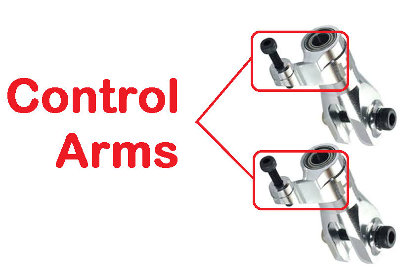
What This Method Does
By removing the linkage balls from each blade grip and aligning the control arms, you can run a straight screw through both threaded holes. If the screw passes cleanly through both grips, the control arms are aligned and very likely not bent. If the screw binds, won't enter the second grip, or angles noticeably, you may have a bent arm or distorted head geometry.
Tools and Parts You'll Need
- Hex driver / screwdriver: Correct size for your blade grip linkage ball screws.
- Straight screw or rod: Same thread size as the linkage ball screws, long enough to pass through both grips (typically a long machine screw).
- Clean work surface: Well-lit bench or table.
- Optional: Calipers or a straight edge to double-check alignment visually.
Step-by-Step Procedure
Step 1: Make the Helicopter Safe
- Disconnect the battery: Unplug the LiPo and set it aside on a non-flammable surface.
- Power down: Turn off the transmitter and ensure the receiver is off.
- Remove the canopy: If needed, remove the canopy for better access to the head.
Step 2: Remove the Main Blades
- Support the helicopter: Place it on a stable, flat surface.
- Unscrew the blade bolts: Remove the bolts or screws holding each main blade in the grips.
- Take off the blades: Set the blades aside so only the bare blade grips remain on the head.
Step 3: Remove the Linkage Balls from the Blade Grips
- Identify the linkage balls: Locate the ball links on each blade grip control arm (where the pitch links attach).
- Detach the links: Carefully pop the ball links off the balls using your fingers or a small tool, avoiding excessive force.
- Unscrew the balls: Using the correct driver, remove the linkage ball screws from each blade grip. You should now have two threaded holes-one in each grip-where the balls were mounted.
Step 4: Align the Blade Grip Control Arms
- Rotate the grips: Gently rotate both blade grips so their control arms are facing each other.
- Match their position: Align the arms so they are directly opposite and as parallel as possible, forming a straight line across the head.
- Stabilize the head: Hold the head or grips steady so the alignment doesn't shift while you perform the test.
Step 5: Run the Screw Through Both Threaded Holes
- Choose a straight screw: Use a long, straight machine screw that matches the thread of the linkage ball holes.
- Start from one side: Insert the screw into the threaded hole of the first blade grip and gently turn it in.
- Continue into the second grip: As the screw advances, guide it toward the threaded hole in the opposite blade grip control arm.
- Check the fit: If the arms are properly aligned and not bent, the screw should pass cleanly through both threaded holes without forcing, cross-threading, or angling.
Interpreting the Results
- Screw passes smoothly: If the screw threads into both grips in a straight line and turns freely, the control arms are very likely straight and correctly aligned.
- Screw binds or won't enter the second hole: This suggests one or both control arms may be bent, or the head assembly has shifted. Inspect the grips, feathering shaft, and head block for damage.
- Visible angle or offset: If you can see the screw entering at an angle or the second hole is noticeably off-center, treat it as a sign of distortion and investigate further before flying.
Step 6: Reassemble the Rotor Head
- Remove the test screw: Carefully back the screw out of both grips.
- Reinstall linkage balls: Screw the linkage balls back into their original threaded holes and tighten them securely (but do not overtighten into plastic).
- Reconnect the links: Snap the ball links back onto the balls, ensuring each link moves freely without binding.
- Reinstall the main blades: Mount the blades back into the grips, tighten the blade bolts, and verify proper tension.
Final Checks Before Flight
- Spin test: Slowly rotate the head by hand and watch for wobble or uneven movement.
- Linkage freedom: Move the collective and cyclic controls (with the battery still disconnected) to confirm smooth linkage motion.
- Visual inspection: Look over the main shaft, feathering shaft, and head block for any remaining signs of damage.
Using this simple alignment and screw-through test gives you a reliable way to detect bent blade grip control arms that might otherwise go unnoticed. It's a quick addition to your post-crash inspection routine that can save you from vibration, poor tracking, and another unexpected crash.