
Demystifying IMUs in STM32 Flight Controllers: The Core of RC Aircraft Stability
In modern RC aircraft stabilization technology, the flight controller (FC) acts as the central brain. At the heart of this brain sits an STM32 microcontroller working in tandem with an Inertial Measurement Unit (IMU). The IMU, which typically houses a 3-axis gyroscope and a 3-axis accelerometer, feeds the microcontroller raw motion data. The STM32 processes this data via Proportional-Integral-Derivative (PID) loops hundreds or thousands of times per second to keep a multirotor level, stable, and responsive to pilot inputs.

How the IMU Interacts with STM32 Hardware
The performance of a flight controller depends heavily on the communication highway between the IMU chip and the STM32 processor. While older or simpler configurations utilize the I2C bus, high-performance flight controllers overwhelmingly demand SPI (Serial Peripheral Interface) communication. SPI supports much higher clock speeds (often exceeding 10-20 MHz), ensuring that sensor data is transferred to the STM32 with microsecond-level latency. Any delay or bottleneck in this pipeline results in delayed PID corrections, translating to "washout," propwash oscillations, or a disconnected flight feel.
Why Gyroscope Performance Matters
A multirotor does not care about its absolute position as much as it cares about its angular velocity-how fast it is rotating along the pitch, roll, and yaw axes. This is the domain of the gyroscope. If the gyroscope yields a noisy, unstable signal, the flight controller perceives mechanical vibrations as actual craft movement. The STM32 will try to correct for this phantom movement, rapidly driving the motors, causing them to overheat, and degrading flight performance.
Key Factors Affecting Gyro Performance
1. Manufacturer and Internal Architecture
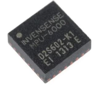
The manufacturing process and internal Micro-Electro-Mechanical Systems (MEMS) design differ drastically across chipmakers. Historically, InvenSense (now TDK) dominated the market with sensors like the legendary MPU6000, praised for its mechanical resilience. Newer players like Bosch (with the BMI series) utilize unique internal structures that handle high-frequency kinetic impacts differently, altering how the sensor perceives frame resonance.
2. Sensor Model and Silicon Generation
Sensor generation introduces major performance leaps. Older legacy chips were susceptible to high-frequency motor noise, requiring pilots to heavily rely on software-side gyroscopic filtering (like RPM filters and dynamic notch filters) inside Betaflight or INAV. Modern flagship models feature built-in hardware anti-aliasing filters and superior resonance rejection right on the silicon wrapper, lightening the math load on the STM32 processor.
3. Sample Rates and Overclocking Limits
Sampling rate defines how many times per second the IMU reads physical motion. Legacy sensors comfortably capped out at 8kHz sampling. Cutting-edge chips can sample natively up to 32kHz or utilize internal interpolation engines. Higher sample rates allow the STM32 to capture a much higher resolution picture of flight dynamics, enabling ultra-precise filter calculations. However, higher rates also generate more data noise, meaning a higher sampling rate is only effective if backed by clean hardware design.
4. Silicon Quality and Noise Floors
Every IMU features an inherent noise floor-the chaotic electrical variations output by the chip even when sitting perfectly still on a desk. A low noise floor means the chip produces a clean, crisp baseline signal. Lower quality sensors require aggressive software low-pass filtering. Because filtering introduces phase delay (a tiny lag between the physical event and the PID loop response), high-quality silicon with a low native noise floor allows for less filtering, resulting in sharper, more locked-in flight characteristics.
5. Temperature Stability
Drones operate in volatile thermal environments; electronics warm up rapidly during flight, and outdoor ambient temperatures change. As a chip heats up, its internal MEMS components expand slightly, causing the gyroscope's baseline to drift (known as thermal drift). A sensor with poor temperature stability will drift mid-flight, making the aircraft slowly lean or pull to one side. High-tier IMUs feature internal hardware temperature compensation to mitigate this anomaly entirely.
IMU Comparison for Flight Controllers
The following breakdown highlights how the industry's most prominent legacy and modern IMU chips compare across core metrics:
| Feature | MPU6000 | ICM-20689 | BMI270 | ICM42688-P |
|---|---|---|---|---|
| Gyroscope Performance | Good | Good | Good | Excellent |
| Accelerometer Performance | Good | Good | Good | Excellent |
| Resolution | Comparable | Comparable | Improved (Varies) | Improved |
| Sampling Rate | Competitive | Competitive | Higher (Varies) | High |
| Temperature Stability | Stable | Stable | Improved (Varies) | Improved |
| Noise Level | Acceptable | Acceptable | Reduced (Varies) | Low |
| Power Consumption | Standard | Standard | Optimized (Varies) | Optimized |
| Advanced Features | Standard | Standard | Advanced (Varies) | Advanced |
| Integration Complexity | Established | Established | Varies | Established |
- For BMI270 and ICM42688-P, specific variants may have different performance characteristics. Refer to individual datasheets for detailed specifications.
- The term "Improved" or "Advanced" indicates a relative enhancement compared to the other sensors in the list.