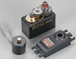
Flybarless Servo & Controller Wiring Masterclass: Pinout Maps for iKON, VBar, Nexus F7 & More
Wiring an RC helicopter flybarless (FBL) flight controller requires absolute precision. Connecting a cyclic servo, rudder tail servo, electronic speed controller (ESC) throttle wire, or telemetry bus to the wrong port can lead to swashplate binding, control reversed channels, or catastrophic electrical damage during initial bench power-up. This master reference guide details official port assignments, pinout mappings, and swashplate connection sequences across the industry's most popular legacy and open-source flybarless units.
Contents
Core FBL Port Mapping Principles
Whether you are configuring a 120-degree eCCPM swashplate on a 700-class competition machine or a micro 450 platform, modern flybarless controllers follow standardized port mapping logic for cyclic pitch, roll, collective, and tail stabilization:
- Cyclic Servos (CH1, CH2, CH3): Standard 120-degree swashplates map Elevator to CH1 (Center/Aft or Center/Fore), Left Aileron to CH2, and Right Aileron/Pitch to CH3. Always verify swashplate geometry in your FBL software wizard before attaching servo arms.
- Rudder Servo (CH4 / Tail): Dedicated high-speed tail servos require exact pulse frequency matching (e.g., 1520µs standard or 760µs narrow-band ultra-high frequency). Never plug a 760µs tail servo into an unconfigured 1520µs port to prevent coil burnout.
- ESC / Throttle (CH5 / Aux): Drives the main motor governor or ESC throttle signal line. On telemetry-enabled setups, telemetry RX/TX pins interface directly with your ESC (YGE, Hobbywing, Tribunus, Kontronik) to pass real-time RPM, current, and voltage back to your transmitter.
iKON / Brain2 Port Mapping
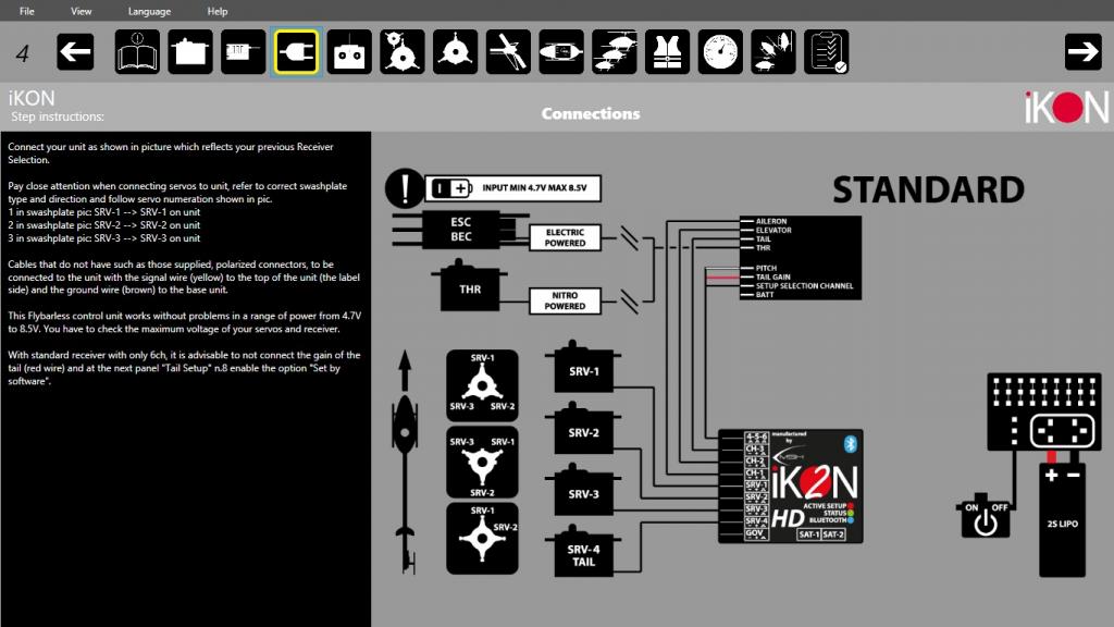
The MSH iKON and Brain2 platforms utilize a clean, front-facing 3-pin connector layout for primary servos, telemetry, and governor input:
| Port Label | Primary Assignment | Auxiliary / Telemetry Function |
|---|---|---|
| CH1 | Elevator Servo (Swash Position 1) | Standard 3-Pin Servo Lead |
| CH2 | Left Aileron Servo (Swash Position 2) | Standard 3-Pin Servo Lead |
| CH3 | Right Aileron / Pitch Servo (Swash Position 3) | Standard 3-Pin Servo Lead |
| CH4 / Tail | High-Speed Rudder Tail Servo | Supports 1520µs, 960µs, and 760µs narrow-band tail servos |
| CH5 / AUX1 | ESC Throttle Output / Motor Governor | RPM Signal Input / ESC Telemetry Interface |
| 4-Pin JST-ZH | SYS / IO Bus | Bluetooth Module / USB Configurator Link |
Mikado VBar / Kbar Setup
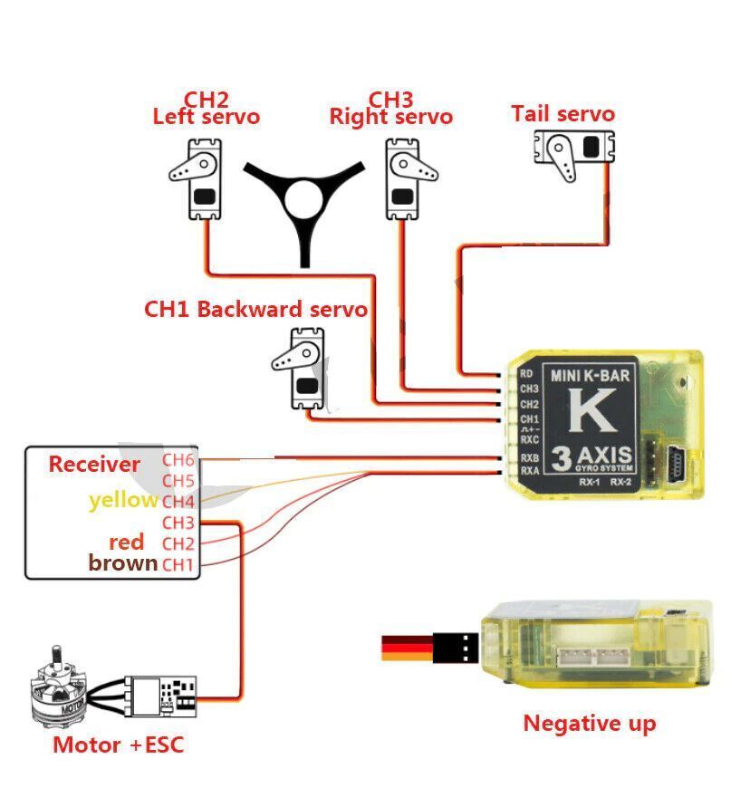
The legacy Mikado VBar and Kbar (Mini VBar) units feature top-entry 3-pin headers labeled specifically for cyclic, tail, and receiver inputs:
| Port Label | Servo / Channel Function | Notes |
|---|---|---|
| RD | Rudder Tail Servo Output | Dedicated 760µs / 1520µs tail servo header |
| Ch1 | Swashplate Servo 1 (Elevator) | Primary cyclic control channel |
| Ch2 | Swashplate Servo 2 (Aileron) | Primary cyclic control channel |
| Ch3 | Swashplate Servo 3 (Pitch) | Primary cyclic control channel |
| RX A / RX 1 | Satellite / Single-Line RX Input | DSM2/DSMX Satellite or S.BUS single-line receiver link |
FlyWing & GPS Autopilot Wiring
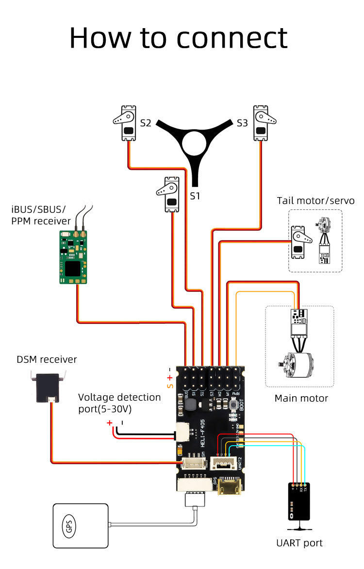
FlyWing H1 and GPS-assisted helicopter flight controllers integrate return-to-home (RTH), optical flow sensors, and compass modules alongside standard collective pitch controls:
| Port Designation | Hardware Connection | Signal Type |
|---|---|---|
| Servo 1 - 3 | Swashplate Servos (Ail / Ele / Pitch) | PWM Output (50Hz - 333Hz) |
| Tail | Tail Servo or Tail ESC (Direct Drive) | PWM / High-Frequency Digital Signal |
| GPS / Compass | Multi-Constellation M8N/M10 GPS Module | Dedicated Serial Communication Bus |
| S.BUS / SBUS | Radio Receiver Bus | Single-cable S.BUS / CRSF serial receiver input |
FlyDragon F722 V2 Rotorflight Mapping
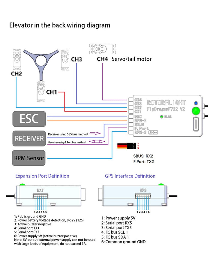
Engineered specifically for Rotorflight open-source firmware, the FlyDragon F722 V2 features an STM32F722 processor and dedicated pad groups for multi-servo swashplate configurations:
| Rotorflight Target Pin | Hardware Output Pad | Function Assignment |
|---|---|---|
| S1 | PWM Output 1 | Swashplate Servo 1 (Cyclic Aileron) |
| S2 | PWM Output 2 | Swashplate Servo 2 (Cyclic Elevator) |
| S3 | PWM Output 3 | Swashplate Servo 3 (Cyclic Pitch) |
| S4 | PWM Output 4 | Tail Rotor Servo / Tail ESC |
| S5 / S6 | PWM Output 5 & 6 | Main ESC Throttle Output / RPM Telemetry Input |
| UART2 / RX2 | Serial RX Pad | CRSF / ELRS Receiver Bus |
Matek G474-HELI Pinout Reference
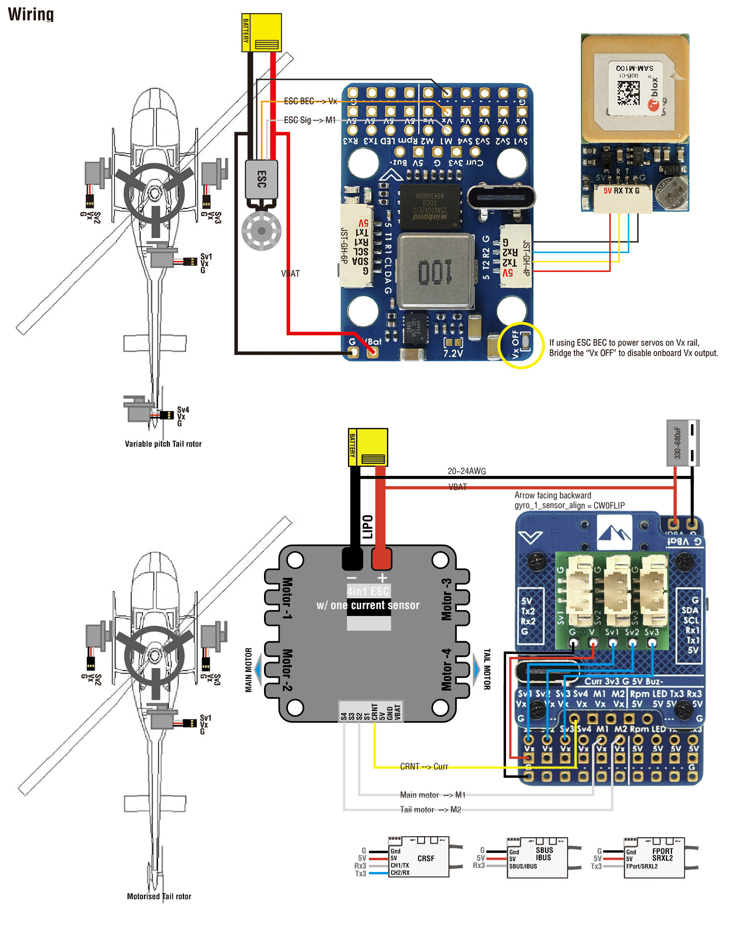
The Matek G474-HELI is a dedicated STM32G474-based hardware platform purpose-built for Rotorflight 2.0+, featuring built-in current sensors, dual BEC voltage outputs, and clean direct-solder pads:
| Matek Pad Label | Rotorflight Function | Recommended Connection |
|---|---|---|
| S1 - S3 | Swashplate Servos 1, 2, 3 | Cyclic servos powered via BEC rail (5V–8.4V) |
| S4 | Tail Rotor Servo | Dedicated high-speed tail servo pad |
| S5 | Main ESC Throttle Output | Connect to ESC Signal wire |
| RPM | Frequency / RPM Sensor | Connect to ESC RPM phase sensor output wire |
| Rx2 / Tx2 | CRSF / ELRS Serial Link | ExpressLRS / Crossfire Receiver UART connection |
RadioMaster Nexus F7 Rotorflight Setup
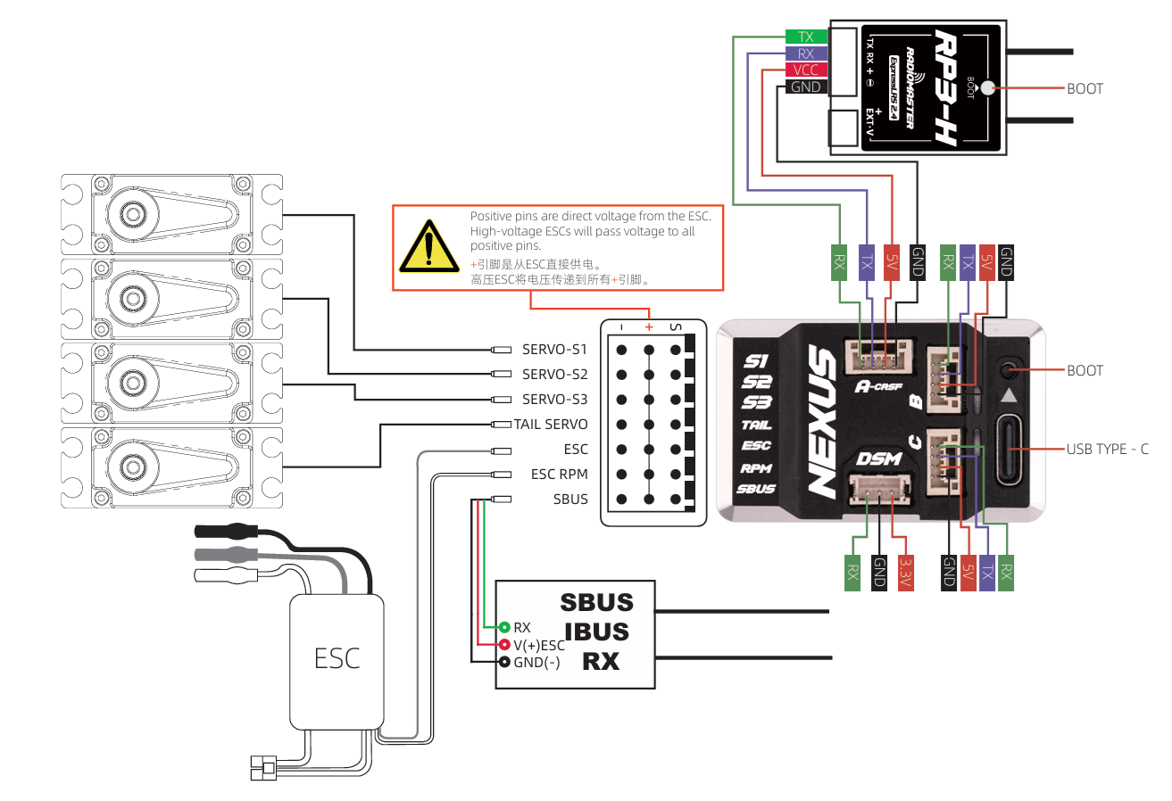
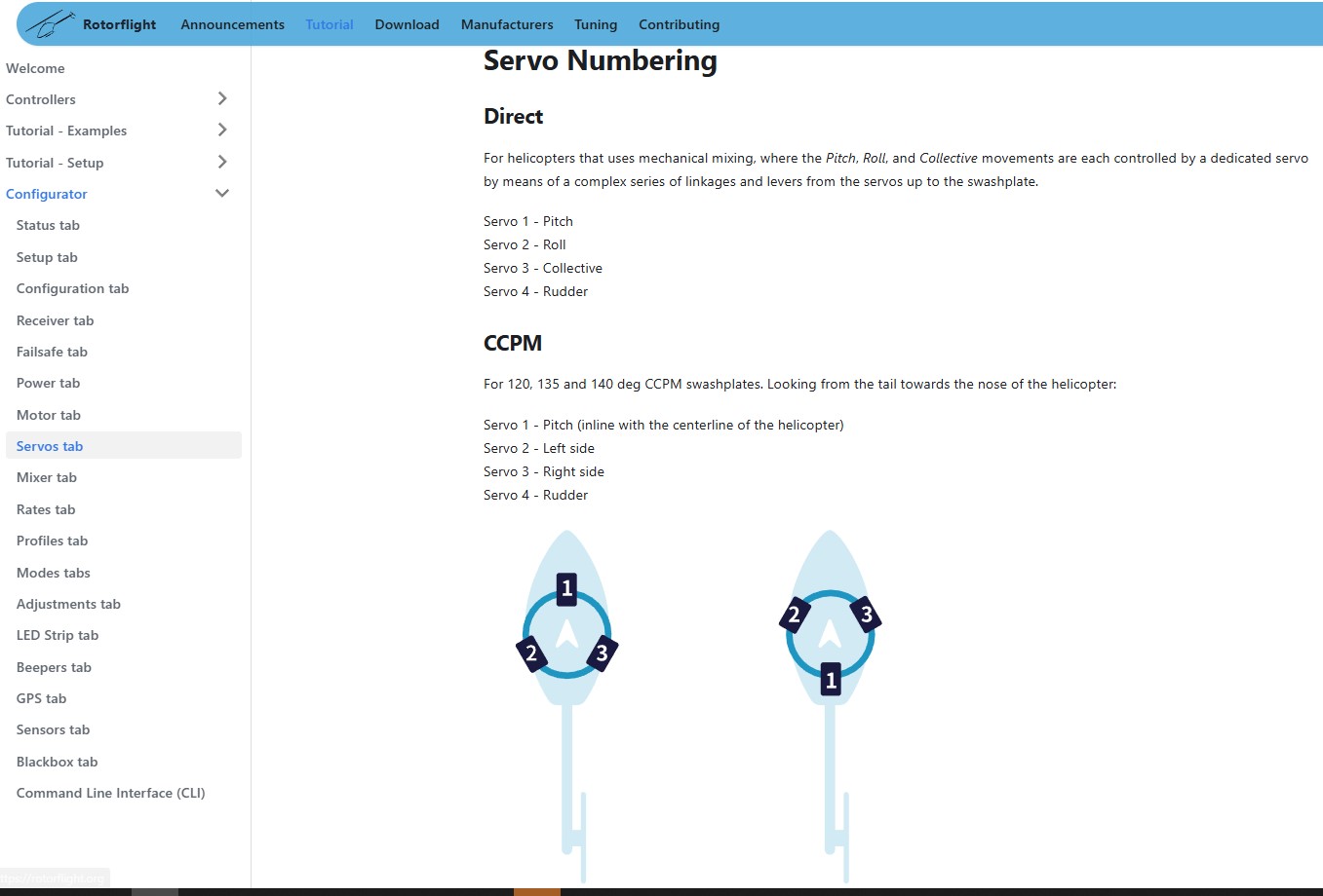
The RadioMaster Nexus F7 is an all-in-one aluminum-cased flight controller optimized for Rotorflight 2. It features locking JST-GH connector ports for plug-and-play installation without custom soldering:
| Nexus F7 Port | Signal Pad | Rotorflight 2 Configurator Channel |
|---|---|---|
| Servo Port 1 | S1 | Cyclic Servo 1 (Aileron) |
| Servo Port 2 | S2 | Cyclic Servo 2 (Elevator) |
| Servo Port 3 | S3 | Cyclic Servo 3 (Pitch) |
| Servo Port 4 | S4 | Tail Servo Output |
| ESC Port | S5 / RPM / Tx4 | ESC Throttle, RPM Telemetry, and ESC Telemetry (Hobbywing/YGE/APD) |
| Receiver Port | Rx1 / Tx1 / 5V / GND | ELRS / CRSF Serial Receiver Port |
Official Manuals & Setup Tools
Download the latest Configurator GUI and view pinout maps for Nexus F7, Matek, and FlyDragon hardware targets.
Access official wiring schematics, governor setup guides, and telemetry integration software for iKON and Brain units.
View complete port mapping diagrams, receiver satellite setup procedures, and governor sensor wiring for VBar controllers.
Additional Builder Guides
-
ESC Telemetry Wiring:
Step-by-step guides for connecting telemetry signal wires from Hobbywing v4/v5, YGE, and Kontronik ESCs to Rotorflight UART pads.
-
Tail Servo Frequency Reference:
Lookup tables for setting correct operating frequencies (333Hz, 560Hz, 760µs) to prevent servo overheating during setup.
-
Swashplate Leveling Procedures:
Comprehensive zero-pitch mechanical alignment guides for 120°, 135°, and 140° swashplate geometry configurations.