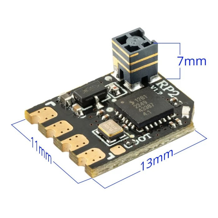
TCXO: Mastering Precision Timing
The Engineering, Circuit Dynamics, and Evolutionary History of TCXO Technology

In modern high-frequency telecommunications-such as ExpressLRS (ELRS) radio control links-packet rates exceed 500Hz to 1000Hz while operating on narrow channel bandwidths. At these extreme frame rates, timing synchronization between the transmitter and receiver is measured in microseconds. A minor shift in carrier frequency will result in packet loss, telemetry warnings, or unrecoverable lock-outs.
At the heart of high-reliability radio gear sits the TCXO (Temperature Compensated Crystal Oscillator). Understanding how TCXOs function requires diving into crystal physics, circuit-level voltage tuning, historical evolution, and real-world temperature behavior.
1. The Physics: Why Temperature Distorts Radio Signals
Every radio transmitter and receiver uses an oscillator to generate a stable high-frequency carrier wave. Standard oscillators rely on a piece of synthetic quartz crystal cut to micro-millimeter precision. Quartz is piezoelectric: applying an electric voltage deforms the crystal, and mechanical flexing generates an electrical charge back. At its natural mechanical resonant frequency, it rings like a high-frequency tuning fork.
Quartz crystals undergo dimensional and elasticity changes when ambient temperature shifts. As heat rises or cold drops, two thermal phenomena alter frequency:
- Lattice Expansion & Contraction: Heat changes the physical distance between silicon and oxygen atoms in the crystal structure, altering its density and mass distribution.
- Elastic Modulus Changes: Temperature alters the mechanical stiffness (Young's Modulus) of the quartz material. A stiffer crystal vibrates faster; a softer, heated crystal vibrates slower.
For standard AT-cut quartz crystals (the most common cut used in RF equipment), the frequency-versus-temperature response forms a 3rd-order polynomial curve (a cubic function):
Left uncompensated, a standard crystal can drift by ±20 to ±50 ppm (parts per million) across a temperature sweep from -20°C to +70°C. In a 2.4GHz or 900MHz link, a 30 ppm drift shifts the carrier frequency by over 72 kHz-enough to push the signal entirely outside the narrow receiver filter band, degrading sensitivity or dropping packets completely.
2. Circuit Architecture: What a TCXO Circuit Is Doing
A standard Crystal Oscillator (XO) simply applies power to a crystal and amplifies its resonant output. A TCXO inserts a dynamic, closed-loop analog or digital feedback compensation circuit that counteracts the crystal's natural cubic drift in real time.
The Core Components of a TCXO Circuit
- Temperature Sensor: A high-precision thermistor or embedded semiconductor bandgap sensor continuously monitors the internal die temperature of the crystal package.
- Compensation Network (Polynomial Generator): An analog resistive network or digital ASIC lookup table maps current temperature against a pre-calibrated inverse of the crystal's cubic drift curve. It outputs a precise, dynamically shifting control voltage ($V_{control}$).
- Varactor Diode (Voltage-Variable Capacitor): A semiconductor diode placed in series or parallel with the crystal acting as a voltage-controlled variable capacitor.
- Buffer Amplifier: Isolates the oscillator from downstream RF circuit loads, preventing impedance changes from pulling the frequency.
How It Compensates in Real Time
When the internal sensor detects a temperature change (e.g., the radio transmitter warming up in your hands from 25°C to 45°C), the crystal naturally wants to slow down or speed up along its cubic curve. The compensation engine calculates the exact inverse voltage required and feeds it to the varactor diode.
Changing the voltage across the varactor alters its internal junction capacitance. Because changing the load capacitance of a quartz crystal slightly "pulls" its resonant frequency, the varactor forces the crystal in the exact opposite direction of the thermal drift-canceling out the error and locking frequency stability down to ±0.5 to ±2.0 ppm.
3. The Origins: Where Did TCXO Technology Come From?
The TCXO was not born in modern microelectronics, but rather out of necessity during mid-20th-century military aviation and tactical communications development.
Historical Timeline of Crystal Stabilization
- 1921 (Walter Guyton Cady): Discovers that quartz crystals can stabilize vacuum tube oscillators, replacing bulkier, unstable LC (inductor-capacitor) tanks.
- World War II Radar & Avionics: Radios struggled in high-altitude bombers where temperatures dropped from +30°C on the tarmac to -50°C at 30,000 feet, causing channels to drift off frequency. Early solutions used bulky OCXOs (Oven-Controlled Crystal Oscillators) that heated the crystal in a mini-oven, consuming massive amounts of battery power.
- Late 1950s - 1960s (Birth of TCXO): Military tactical radios and satellite tracking required instant-on frequency accuracy without the heavy power draw and warmup delays of heated ovens. Engineers pioneered network compensation circuits using temperature-sensitive resistors (thermistors) paired with voltage-variable capacitors to dynamically correct frequencies without heating elements.
- 1990s - Present (Digital TCXOs & Consumer Scale): Mobile cellular networks (2G/3G/GSM) and GPS receivers required ultra-compact, cheap TCXOs. This drove TCXO miniaturization into sub-millimeter surface-mount device (SMD) packages with integrated silicon ASICs.
4. Where Else Is TCXO Tech Used?
TCXO components are ubiquitous across industries where precise timing, long-range RF, or clock synchronization are paramount:
| Industry / Application | Why TCXO Is Required |
|---|---|
| GPS / GNSS Receivers | Satellite triangulation calculates position by measuring the time-of-flight of radio signals traveling at the speed of light. A nanosecond error distorts distance calculations by feet. |
| Cellular Base Stations & 5G | Requires tight time-division duplexing (TDD) synchronicity so thousands of mobile devices can share frequencies without overlapping channels. |
| Aerospace & Defense Systems | Tactical radios, missile guidance, and drone telemetry operating across extreme thermal variations (desert heat to high-altitude freezing). |
| Automotive Radar & V2X | 77GHz collision avoidance radars and vehicle-to-everything communications must maintain rock-solid clock rates across summer engine bay heat and freezing winter conditions. |
5. TCXO in Radio Control (e.g., RadioMaster & ExpressLRS)
In modern high-performance RC transmitters and receiver modules, TCXO chips have shifted from a luxury component to a baseline standard for several key reasons:
- Thermal Drift Under High RF Output: When an RC transmitter operates at 1 Watt or 2 Watts of telemetry output power, internal power amplifiers generate significant localized heat inside the hand controller case. A standard crystal drift causes packet loss; a TCXO remains stable regardless of internal heat buildup.
- Cold-Weather Flying: Flying in sub-zero winter ambient conditions causes standard uncompensated crystals to drift significantly out of tune, leading to unexpected telemetry warnings or link degradation.
- High Packet Rates (500Hz - 1000Hz): High update rates require razor-thin timing windows for packet transmission and reception. Microsecond timing drifts can cause phase misalignment between the radio module and the receiver.
- Narrowband Long-Range Telemetry: Long-range links operate near the noise floor. Keeping the RF carrier perfectly centered allows receivers to run tight channel filters that block surrounding interference while pulling weak signals out of the air.