Building a Custom 6S 5000mAh Battery Pack
Assembling a custom high-discharge battery pack for demanding applications like high-performance RC helicopters requires precision, patience, and the right equipment. Whether you are building with high-capacity cylindrical cells or custom pouch setups, a well-built 6-cell (6S) pack ensures consistent voltage delivery, proper thermal management, and reliable high-current output under aggressive collective pitch transients.
In this guide, we walk through the step-by-step process of constructing a robust 6S 5000mAh battery pack equipped with heavy-duty ASA 150 connectors, complete with shock-absorbing foam layering, balanced wiring, and protective insulation.
1. Gathering Materials and Workspace Preparation
Before beginning assembly, lay out all necessary components, tools, and safety gear. Having an organized workbench prevents mistakes and ensures clean, repeatable solder joints.
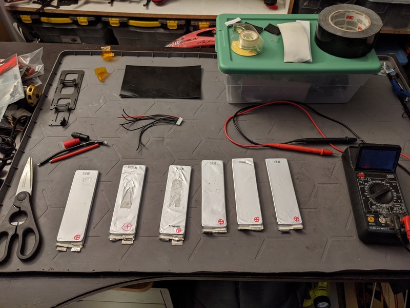
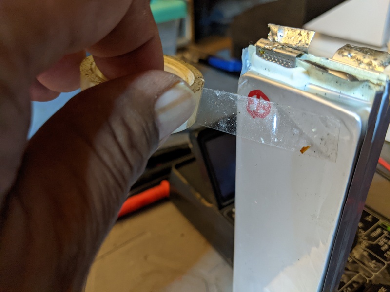
The foundational step in physically securing the cells together involves preparing the cell array layout. Using double-sided scotch tape between the cell bodies creates a solid, stable block that resists shifting under high-G maneuvers in flight.
2. Series Configuration and Soldering Setup
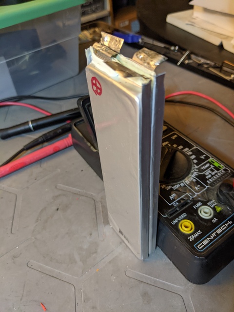
With the physical block aligned, building the series connections begins. Careful attention must be paid to cell orientation (alternating or sequential depending on bus bar / nickel strip configuration) to achieve the target series connected 6S voltage.
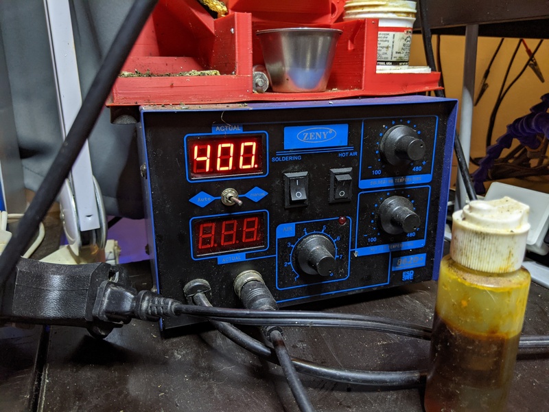
Reliable soldering on battery tabs requires steady, high heat to prevent heat soak into the core of the cell. The soldering station is set up and brought to a stable 400°C to ensure quick, clean joints.
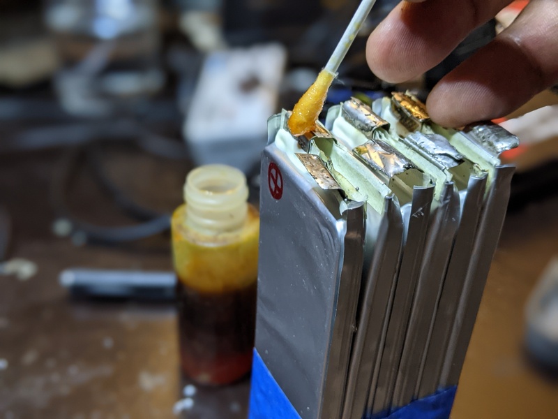
Because battery tabs and nickel/copper interconnects can resist solder adhesion, specialized aluminum/metal soldering flux is applied to clean oxide layers and promote a permanent metallurgical bond.
3. Progressive Assembly and Voltage Verification
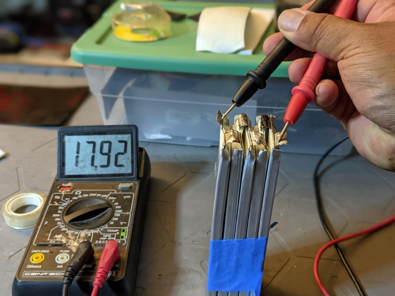
As each cell is integrated into the series string, systematic multimeter checks are mandatory to verify proper incremental voltage increases (e.g., adding ~3.6V to 4.2V per step depending on storage or nominal state).
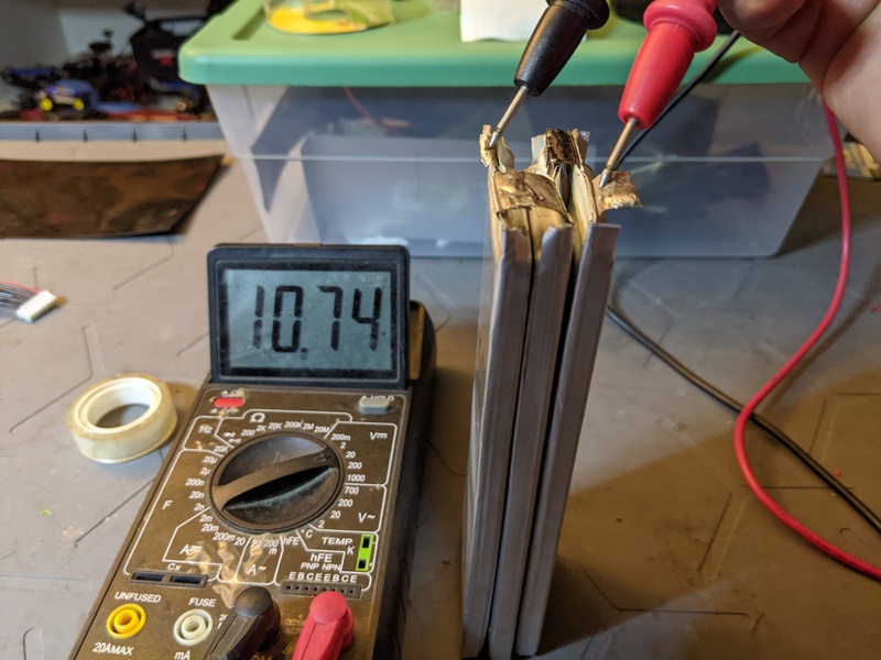
Continuing down the line, the fourth cell is integrated, maintaining strict polarity checks and mechanical alignment.
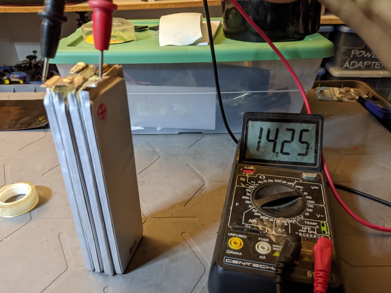
The progression reaches the penultimate stage with the fifth cell installation, ensuring every interconnect is mechanically sound and electrically isolated from adjacent accidental shorts.
4. Vibration Damping and Insulation
RC helicopters subject electronics and power systems to extreme high-frequency vibrations. Integrating shock-absorbing foam between cell walls protects the structure from fatigue cracking.
5. Balance Lead Wiring and Harness Assembly
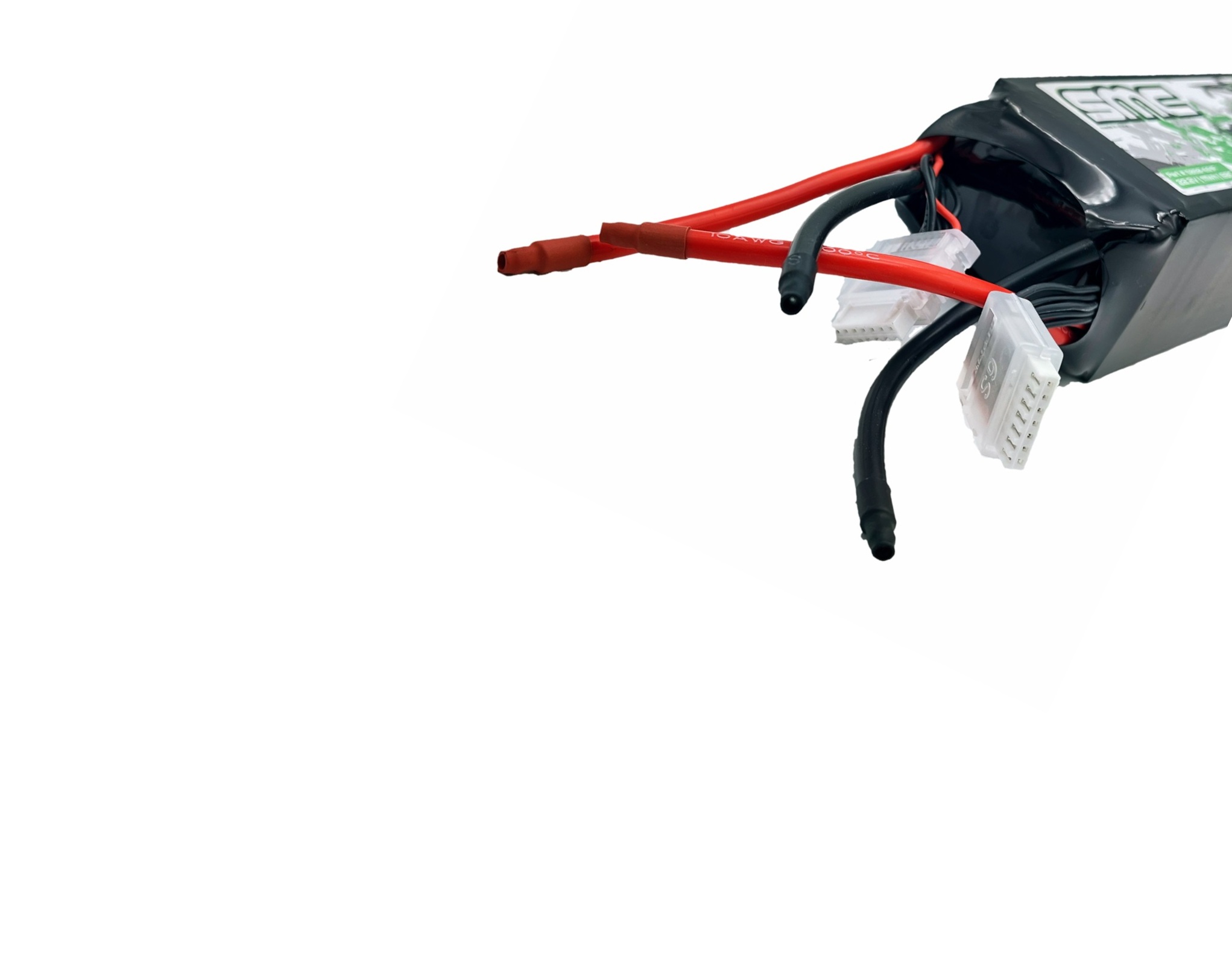
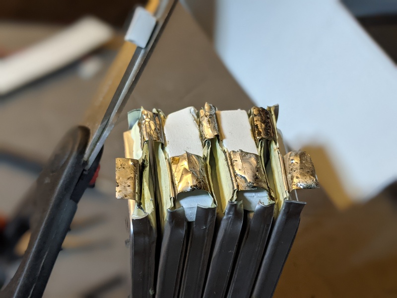
A proper 6S balance harness requires 7 wires (Negative, Cell 1+, Cell 2+, Cell 3+, Cell 4+, Cell 5+, Positive). Each tap point must be soldered precisely to the correct series junction.
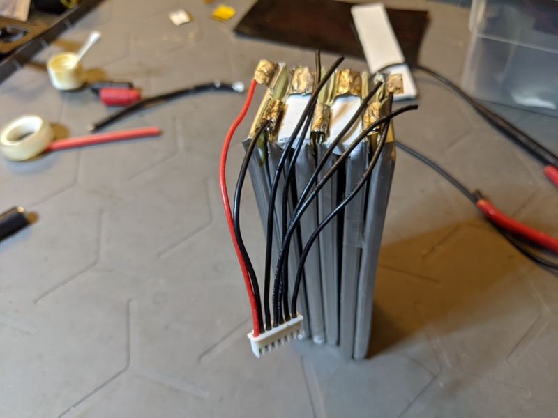
With all balance wires routed, soldered, and strain-relieved, the balancer plug harness is fully completed and checked for pinout correctness.
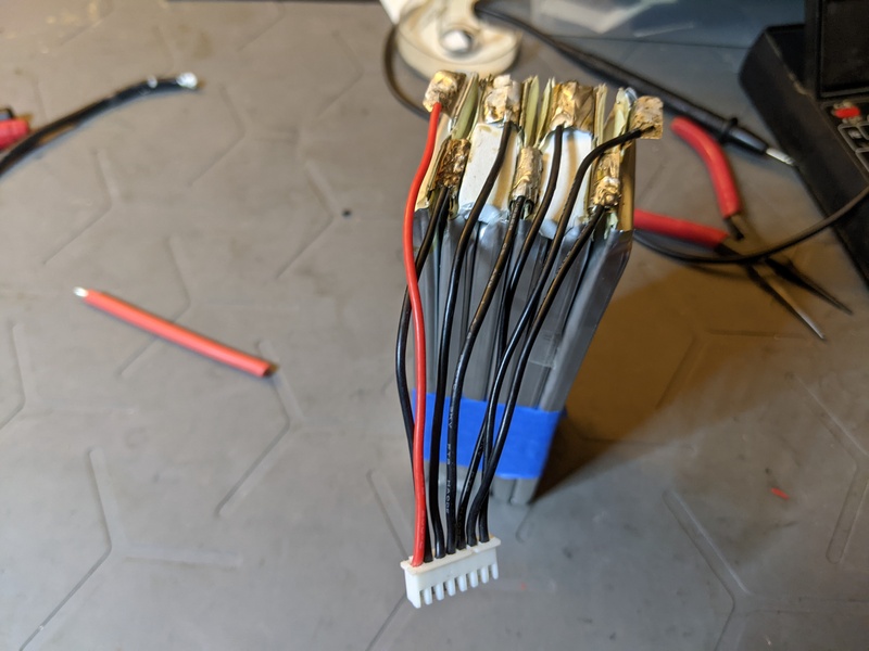
6. Applying Klaxton Tape
Exposed tabs and bus bars present short-circuit hazards so after installing the main leads (The thick 8-gauge black/red wires seen in the pic), we apply high-temperature polyimide (Kapton) tape strategically across sensitive areas to provide robust electrical insulation and thermal protection.
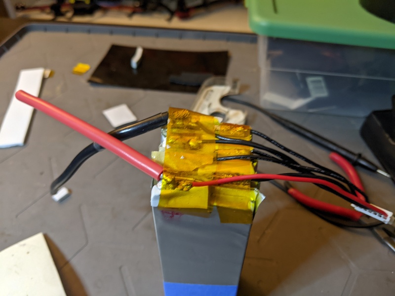
7. Foam padding and duct tape to hold it down
To keep the cushioning foam and padding securely fixed around the pack geometry before final wrapping, reinforcement tape is applied.
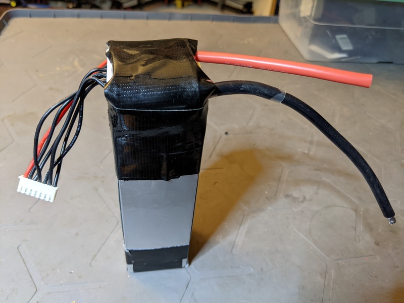
8. Initial Testing and Final Finish
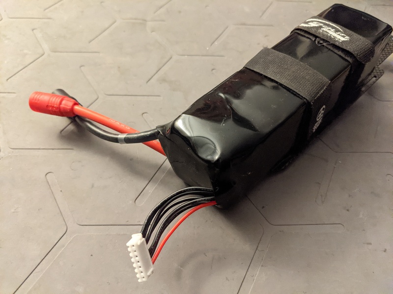
Before applying final shrink wrap, connect the pack to a smart charger or battery analyzer for an initial voltage check across both the main heavy-duty ASA 150 power leads and the balance tap.
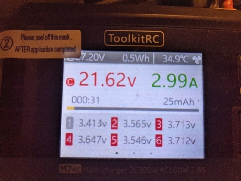
Once electrical integrity is fully confirmed, heavy-wall heat shrink tubing is applied over the entire assembly and shrunk evenly with a heat gun to yield a professional, rugged, moisture-resistant finished pack.