The Throttle Jockey Governor: History, Architecture, and Technical Mechanics
1. Introduction and Historical Context
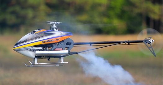
Manufactured by Model Avionics, the Throttle Jockey series (alongside its later siblings, the RevMax and Throttle Max) stands as a legendary piece of nitro-era RC helicopter history. Released in the late 1990s and heavily refined through the 2000s, it emerged during a time when internal combustion (.30 to .90-size glow engines) ruled competitive 3D aerobatics.
Before advanced computerized transmitters featured built-in governor programming or modern flybarless units integrated high-speed RPM sensing, maintaining a consistent rotor headspeed through violent collective pitch changes was an elusive manual art. Pilots relied purely on steep V-shaped throttle curves. The Throttle Jockey revolutionized the hobby by introducing an affordable, lightweight (weighing a mere 6 grams in its later iterations), highly responsive digital rotor speed governor that actively monitored engine RPM and dynamically overrode throttle curves to maintain a locked-in headspeed.
2. Why It Was Developed
In nitro-powered RC helicopters, rotor headspeed dictates overall collective pitch response, agility, and tail authority. However, aerodynamics pose a massive challenge: when a pilot pulls hard "up collective" to execute a sudden climb or aggressive maneuver, the massive aerodynamic drag on the main rotor blades bogs the engine down. Conversely, unloading collective causes the engine to scream past its optimal RPM band.
While a transmitter's throttle curve attempts to counteract this by adding throttle at high collective sticks, it cannot react to changing fuel loads, pipe resonance, weather density, or engine tuning inconsistencies. The Throttle Jockey was engineered to close this loop by utilizing real-time feedback from the engine, providing a predictive, adaptive feed-forward control algorithm that instantly applied throttle before the rotor head could bog down.
3. Hardware Architecture & Wiring
The Throttle Jockey system acts as an inline processing bridge between the radio receiver and the throttle servo, while interfacing with a dedicated magnetic RPM sensor mounted near the engine.
- Receiver Connections:
- Throttle Channel: Plugs into the throttle output of the receiver (or throttle channel of the gyro/mixer). The throttle servo then plugs directly into the Throttle Jockey unit.
- Auxiliary / Remote Channel (AUX / Gear - Ch 5 or Ch 7): Used in "Remote Mode" to let the transmitter remotely toggle the governor on/off or set target headspeed rates via travel adjustments (EPA/ATV).
- Power Supply: Powered directly through the receiver bus (typically 4.8V to 6V NiMH or regulated BEC power supplies common to that era).
- Modes of Operation:
- Remote Mode: Target RPM is controlled dynamically via an auxiliary transmitter channel switch.
- Manual Mode: Target RPM is set using a tiny onboard potentiometer (POT) located beneath a small adjustment hole marked "REM" on the unit's case, utilized when the radio system lacked spare auxiliary channels.
4. Sensing Mechanics: Magnets and Hall Effect Sensors
To calculate real-time RPM, the Throttle Jockey relied on a discrete electronic pairing: a rare-earth trigger magnet and a Hall Effect sensor.
- The Magnet: A small, balanced neodymium magnet was mounted flush into the cooling fan of the nitro engine (typically secured with a strong structural fillet of cyanoacrylate glue or epoxy to withstand 20,000+ RPM centrifugal forces).
- The Hall Effect Sensor: The sensor itself was a bare or lightly shrink-wrapped Hall Effect semiconductor switch soldered to a harness. It sat on a custom-trimmed bracket attached to one of the engine mount bolts or crankcase lugs, positioned on the intake or exhaust side where the cooling fan perimeter passed closest.
- How It Worked: As the engine spun, the cooling fan swept the magnet past the face of the Hall Effect sensor once per revolution. The sensor detected the magnetic flux lines and switched state (pulling its output low), sending a clean digital pulse to the Throttle Jockey micro-controller. By measuring the precise microsecond intervals between pulses, the unit calculated instantaneous engine and rotor head RPM.
5. Advanced Feature: The Thermistor Head Temperature Monitor
One of the most innovative engineering features built into advanced iterations of the Throttle Jockey family was its integrated thermistor temperature monitoring capability.
- The Sensor: A small ring-terminal or slip-on thermistor probe was designed to be bolted directly under one of the cylinder head cooling button bolts on the glow engine (such as OS, Yamada, or Magnum engines).
- Thermal Protection: Glow engines are notoriously sensitive to a "lean run," which can cause catastrophic detonation, pinched liners, or dropped-pin bearing failures. The Throttle Jockey's thermistor continuously monitored cylinder head temperatures in real-time.
- Fail-Safe Action: If the engine temperature exceeded a safe, user-defined thermal threshold (signaling a dangerously lean needle valve setting), the governor would automatically intervene by overriding the throttle command and bumping the throttle open or forcing a protective idle behavior, alerting the pilot to land before thermal damage occurred.
6. Calibration and Radio Setup Quirks
Setting up a Throttle Jockey required meticulous radio calibration because the unit needed to map exact pulse-width modulation (PWM) ranges for closed throttle, idle, and full throttle, as well as auxiliary switch thresholds.
- Endpoint Precision: Throttle endpoints (ATV / End Points) had to be set as close to +/-100% as possible to give the processor full resolution.
- The Calibration Dance: Entering calibration mode required a specific ritual involving turning on the receiver while rapidly toggling an auxiliary switch (e.g., the landing gear switch) a set number of times, followed by moving the throttle stick from low to high so the unit could learn the transmitter's limits and store them in non-volatile memory.
- Throttle Priority & Autorotations: Setup protocols mandated that throttle hold had to be configured below the governor's engagement threshold (typically 25% throttle stick position). This ensured that when a pilot flicked into throttle hold for an autorotation, the Throttle Jockey instantly disengaged so it wouldn't fight the user's manual throttle cut commands.
7. Legacy and Impact
The Throttle Jockey established the blueprint for modern electronic governing. While modern flybarless systems (like Rotorflight, Spirit, and VBar) and electric ESCs have integrated RPM sensors and internal governors directly into digital firmware architectures, the foundational engineering principles pioneered by Model Avionics—such as magnetic Hall effect pickup placement, feed-forward RPM response curves, and precise pulse-width translation—paved the way for modern RC precision aerobatics.