
Universal Asynchronous Receiver-Transmitter (UART): History, Technical Architecture, and Ecosystem
1. Introduction and Historical Context
The Universal Asynchronous Receiver-Transmitter (UART) is one of the most enduring communication protocols in electronics. Developed in the 1960s—growing out of earlier telegraphy and teletypewriter standards—the UART was created to solve a fundamental hardware engineering challenge: how to convert parallel data from a computer bus into serial data for transmission over a single wire pair, and vice-versa.
Before the advent of integrated UART microchips, serial communication required complex, discrete logic circuits of flip-flops, shift registers, and clock dividers. In the early 1970s, semiconductor manufacturers integrated these massive logic blocks into single-chip Large Scale Integration (LSI) ICs (such as the Western Digital WD1950 and the legendary MOS Technology 6551 / National Semiconductor NS16450).
UARTs were originally developed to drive teletypewriters (TTYs) and early video terminals communicating with mainframe and minicomputers over long-distance telephone lines via modems. As personal computing emerged, the UART became the foundational engine behind the RS-232 serial port (COM port) on IBM-compatible PCs, handling everything from mouse inputs and dial-up internet connections to industrial automation telemetry.
2. Why It Was Developed
At its core, transmitting data in parallel (e.g., 8 independent wires for an 8-bit byte) is efficient over extremely short distances (like inside a CPU cache or memory bus), but becomes completely impractical over long distances due to:
- Cost and Bulk: Requiring massive multi-conductor cabling.
- Clock Skew: High-frequency signals traveling down parallel wires arrive at slightly different times due to minor physical discrepancies in trace length or capacitance, corrupting the data at the receiver end.
The UART was engineered to serialize parallel data streams so they could be sent reliably over asynchronous physical links using minimal wiring. By embedding synchronization cues directly into the data stream itself, the UART eliminated the need for a dedicated, synchronized clock wire running alongside the data lines.
3. Core Technical Principles: How It Works
A UART is not a communication protocol in the strict OSI network sense (like Ethernet or USB); rather, it is a hardware block or circuit whose primary job is asynchronous serial communication.
- Asynchronous Operation: There is no shared clock wire between the transmitting device and the receiving device. Instead, both devices must be pre-configured to communicate at the exact same agreed-upon speed (the baud rate).
- The Shift Register Core:
- Transmitter (TX): Takes parallel data bytes from the host microcontroller's data bus, loads them into a shift register, and clocks them out bit-by-bit onto the physical TX line.
- Receiver (RX): Samples the incoming physical RX line at precise intervals, shifts the bits back into a holding register, and presents them as a parallel byte to the host system.
- Full-Duplex Communication: Because the TX and RX lines are completely independent, a UART can send and receive data simultaneously without packet collisions.
4. Detailed Protocol & Packet Structure
Because there is no external clock signal to tell the receiver when a bit starts or stops, UART relies on a strict, predetermined framing structure for every single byte transmitted:
[Idle High] [Start Bit (0)] [Data 0..7] [Optional Parity] [Stop Bit(s) (1)] [Idle High]- Idle State: When no data is being transmitted, the physical line is held in a HIGH state (logic level
1). - Start Bit: To signal the beginning of a data packet, the transmitter pulls the line LOW (logic level
0) for the duration of one clock cycle. This alerts the receiver's internal timer to begin sampling. - Data Bits: Immediately following the start bit, 5 to 9 data bits (usually 8 bits, representing a full byte) are transmitted, typically starting with the Least Significant Bit (LSB) first.
- Parity Bit (Optional): An optional error-checking bit.
- Even Parity: The parity bit is set so that the total number of
1s in the data payload plus the parity bit is an even number. - Odd Parity: The total number of
1s is odd.
- Even Parity: The parity bit is set so that the total number of
- Stop Bit(s): The transmitter pulls the line back HIGH for 1, 1.5, or 2 bit-periods. This guarantees a clean transition boundary so the receiver can detect the end of the frame and prepare for the next start bit.
5. Communication Speeds (Baud Rates)
UART communication speeds are measured in baud (symbols per second, which usually equals bits per second at standard configurations). Common legacy and modern baud rates include:
- Legacy speeds: 300, 1200, 2400, 9600, 19200, 38400, 57600 baud.
- Standard modern speeds: 115200 baud (widely used in microcontrollers, GPS modules, and debugging consoles).
- High-speed applications: 230400, 460800, 921600, up to several megabaud (Mbps) in modern high-speed microcontrollers and industrial interfaces.
6. Where We Use It and What Devices Use It
Despite being decades old, the UART is ubiquitous in modern embedded systems and hardware engineering:
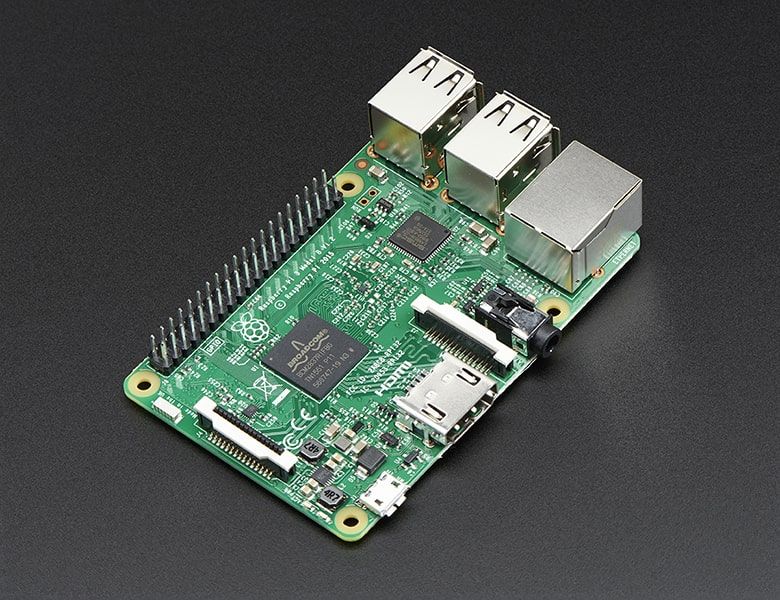
- Microcontrollers & SoC Boards: Arduino, Raspberry Pi, ESP32, STM32, and PIC microcontrollers all feature built-in hardware UART peripherals.
- Debugging Consoles: Almost all embedded Linux boards, routers, and enterprise switches expose a "serial console" port via UART for low-level kernel booting and debugging.
- Peripherals & Sensors: GPS receivers, Bluetooth modules (e.g., HC-05), RFID readers, fingerprint sensors, laser rangefinders, and telemetry radios routinely use UART.
- Industrial & Legacy Systems: CNC machines, programmable logic controllers (PLCs), point-of-sale (POS) receipt printers, and scientific laboratory instruments.
7. What Software Uses It
UART communication interfaces directly with software across multiple layers:
- Operating System Kernel Drivers: Linux kernel serial drivers (
ttyS,ttyAMA,ttyUSB), Windows COM port drivers (serial.sys), and macOS serial communication daemons. - Terminal Emulators: Software used to read and write data over serial links, including PuTTY, minicom, screen, Tera Term, and Arduino Serial Monitor.
- Programming Languages & Libraries:
- Python:
pyserial - C/C++: POSIX
termiosAPI (<termios.h>) - Node.js:
serialportlibrary
- Python:
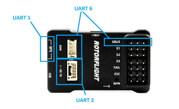
- Flight Controllers & Robotics: Firmware platforms like Betaflight, Cleanflight, ArduPilot, and PX4 use UART ports extensively (labeled as UART1, UART2, etc.) to interface with GPS units, ExpressLRS receivers, compasses, and blackbox loggers.
8. Compatibility with Other Protocols and Transceiver Physical Layers
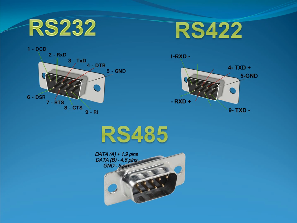
The raw output of a microcontroller's UART pin is TTL/CMOS logic (typically 0V for logic 0 and 3.3V or 5V for logic 1). Because TTL signals degrade rapidly over distance and are highly susceptible to electromagnetic interference, UART logic is frequently paired with external physical-layer transceivers:
- RS-232: Uses voltage swings between +12V and -12V to represent logic states, allowing cable runs up to 15 meters. Requires a level shifter IC like the MAX232.
- RS-485 / RS-422: Uses differential signaling over twisted-pair wire, enabling multi-drop networks up to 1.2 kilometers at high noise immunity. Commonly bridged from UART using chips like the MAX485.
- USB-to-UART Bridges: Modern computers lack native 9-pin serial ports, so USB-to-UART bridge chips (such as CP2102, FT232R, or CH340) translate USB packet streams directly into UART TTL signals for developer boards.
9. Comparison: UART vs. Other Serial Protocols
| Feature | UART | SPI (Serial Peripheral Interface) | I2C (Inter-Integrated Circuit) |
|---|---|---|---|
| Wiring | 2 wires (TX, RX) + Ground | 4 wires (SCLK, MOSI, MISO, CS) + Ground | 2 wires (SDA, SCL) + Ground |
| Clock Architecture | Asynchronous (Baud-rate agreed upon) | Synchronous (Dedicated clock line from Master) | Synchronous (Shared clock line from Master) |
| Topology | Point-to-Point (1-to-1) | Master to Multiple Slaves (via Chip Select) | Multi-Master, Multi-Slave (Addressable bus) |
| Speed | Moderate (Kbps to few Mbps) | Very Fast (Tens of MHz) | Fast (Standard 100kbps, Fast 400kbps, 1Mbps+) |
| Overhead | High (Start/Stop/Parity bits per byte) | None (Pure raw data stream) | Medium (Address frames & ACK/NACK bits) |
10. Is Anything Replacing UART?
While high-speed parallel buses and legacy serial ports have largely vanished from consumer PCs (replaced by USB, PCIe, and Ethernet), UART inside embedded systems is irreplaceable and growing.
In modern microcontrollers, UART is rarely replaced because:
- It requires minimal silicon area on an IC.
- It demands very little software overhead.
- It remains the universal fallback standard for human-readable debugging and chip-to-chip telemetry.
Where high-speed streaming is required inside a device, engineers turn to SPI or MIPI interfaces; but for low-pin-count communication, bootloading, and sensor integration, UART remains an eternal standard.