
Understanding Spread Spectrum Technology: A Guide for RC Pilots
For decades, flying RC aircraft was a high-stakes gamble. Operating on old 72MHz AM/FM bands meant that if another pilot turned on a transmitter on your same channel, your model suffered a catastrophic "glitch" and crashed. Modern 2.4GHz Spread Spectrum technology completely eliminated this issue, allowing dozens of pilots to fly simultaneously without interference.
The Conception and History

The core concept of spread spectrum technology was co-invented during World War II by Hollywood actress Hedy Lamarr and composer George Antheil. Patented in 1942 as a "Secret Communication System," it was originally designed to prevent radio-controlled torpedoes from being jammed by enemy forces.
Antheil, familiar with synchronized player pianos, helped design a mechanism that used punched paper rolls to rapidly hop the radio signal across 88 different frequencies. While the military did not adopt the technology until the 1960s, this foundational concept eventually paved the way for modern Wi-Fi, Bluetooth, and cellular networks.
Lamarr's approach was a primitive form of what is today known as frequency-hopping spread spectrum. For FHSS, a given bandwidth (range of frequencies) is divided into many different distinct channels. Bluetooth, for example, uses the 2.4 - 2.843 Ghz bandwidth, with 79 defined channels. In order to send a signal, the transmitter and receiver must first synchronize on a particular channel and seed value. The transmitter then starts sending its message, only broadcasting for a few hundred milliseconds on any given channel. The transmitter jumps between channels based upon a pseudorandom algorithm; since the receiver knows the starting channel and has the same seed, it can use the same algorithm to follow the jumps and receive the signal. To any device that does not know the jumping sequence, the message is nearly indecipherable. There can be many different FHSS devices broadcasting at the same time in the same area, because when each device is using its own sequence the chance of two of them being on the same channel at the exact same instant is relatively low.
How Spread Spectrum Works
In traditional radio communication, a signal is transmitted on a single, narrow frequency channel. If background noise or another transmitter hits that exact frequency, the signal is lost. Spread spectrum solves this by taking a narrow-band data signal and spreading it across a much wider frequency band.
There are two primary methods used to achieve this:
-
Frequency-Hopping Spread Spectrum (FHSS):
The transmitter and receiver hop together from one frequency to another in a pseudo-random sequence dozens or hundreds of times per second. If a specific frequency is blocked, the system instantly moves to a clean one with virtually zero data loss.
How FHSS Works
- Hopping Pattern: Both the transmitter and receiver share a synchronized, pseudo-random sequence that dictates when and to what frequency the signal will jump next.
- Short Dwell Time: The signal stays on any single frequency channel for only a fraction of a second (milliseconds or microseconds) before hopping away.
- Reconstruction: The receiver tracks the identical hopping pattern to follow the signal and reassemble the data stream correctly.
Main Advantages
- Interference Resistance: If noise or another device blocks one specific frequency, it only affects a tiny sliver of data; the rest of the transmission succeeds on other channels.
- Security and Privacy: Casual eavesdropping is difficult because listeners do not know the precise pseudo-random hopping schedule.
- Shared Spectrum Use: Multiple devices can operate in the same area (such as the 2.4 GHz ISM band used by Bluetooth) without stepping on each other permanently.
-
Direct-Sequence Spread Spectrum (DSSS):
Instead of hopping, the signal is combined with a redundant bit pattern called a "chipping code" and transmitted across a wide, continuous channel. The receiver uses the same code to reconstruct the original signal, easily filtering out any background noise.
Direct-sequence spread spectrum (DSSS) is a wireless modulation technique that broadens a signal's bandwidth by multiplying the original data bits with a fast-moving, pseudo-random digital code.
How DSSS Works
- Chipping Code: The transmitter combines each data bit with a high-speed string of binary bits called a "chipping code" or "pseudo-random noise" (PN) sequence.
- Bandwidth Expansion: This multiplication speeds up the overall signal transmission rate, which spreads the signal across a much wider radio frequency spectrum.
- Despreading: The receiver uses the exact same PN sequence to reverse the multiplication, collapsing the wide signal back into the original narrow data stream.
Main Advantages
- Noise Resistance: Environmental noise or jamming signals only affect a tiny fraction of the wideband transmission, leaving the recovered data mostly intact.
- Low Signal Profile: Spreading the signal drops its power density near or below the natural background noise floor, making it hard for unauthorized parties to detect.
- Multipath Mitigation: The receiver can easily isolate the direct signal from delayed reflections (echoes) bouncing off walls or buildings because their timing will not match the PN code.
- High Throughput: DSSS continuously uses the entire allocated bandwidth, which generally allows for higher data speeds than hopping methods under stable conditions.
Imagine trying to scream a sentence across a noisy room on one single breath (Traditional RF). If someone coughs at that exact moment, the listener misses the message. Now imagine repeating every single word three times across different pitches (Spread Spectrum). Even if static blocks a few words, the listener easily reconstructs your entire sentence, ensuring your RC aircraft never misses a critical aileron or elevator input.
The Handshake: How the Binding Process Works
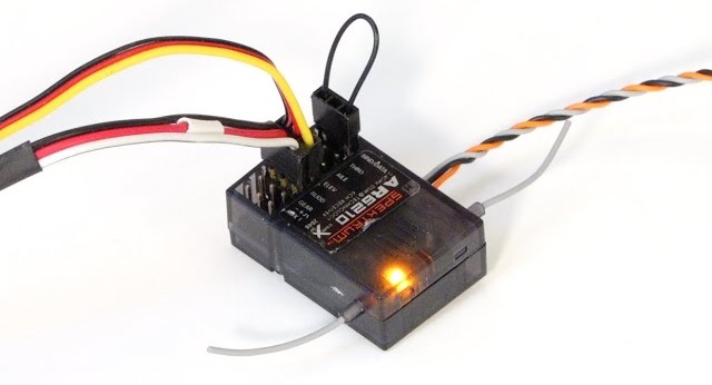
Because dozens of transmitters are broadcasting on the 2.4GHz band simultaneously at a busy flight line, your receiver needs a way to filter out every radio except your own. This security measure is achieved through binding.
Every modern 2.4GHz transmitter is manufactured with a globally unique, hardcoded identification number, often referred to as a GUID (Globally Unique Identifier). When you put a receiver into "bind mode" (typically via a physical bind plug, a button press, or a software menu), it opens a wide, unprotected listening channel. When the transmitter is turned on in bind mode, it broadcasts its unique GUID alongside a specific coordination key.
The receiver intercepts this GUID and permanently saves it to its internal EEPROM memory. Once saved, the receiver closes its open listening channel. From that exact millisecond forward, the receiver acts like a lock that can only be opened by the key containing that specific transmitter ID, completely ignoring commands from any other radio on the field.
Behind the Scenes: Normal Flight Operation
Once bound and powered up for a normal flight, the transmitter (Tx) and receiver (Rx) engage in a highly coordinated dance to maintain a seamless control link:
-
Algorithmic Synchronization:
During the initial binding handshake, the Tx and Rx agreed upon a mathematically generated "hopping table" based on the Tx's unique ID. During flight, both modules use this identical mathematical formula to calculate exactly which frequency to switch to next, hopping in absolute synchronization up to hundreds of times per second.
-
Packetized Control Commands:
Your stick movements are not sent as continuous analogue waves. Instead, the Tx samples your gimbals, converts the positions into digital values (e.g., standard PWM or digital serial values), packages them into a tiny digital data packet, appends its unique GUID, and broadcasts it.
-
Validation and Execution:
Upon receiving a packet, the Rx checks the embedded GUID. If it matches, the Rx extracts the servo positions, verifies the packet isn't corrupted using an error-checking algorithm (like a Cyclic Redundancy Check), and instantly updates your flybarless (FBL) system or servos. If a packet is corrupted due to momentary interference, the Rx drops it and waits a few milliseconds for the next hop, resulting in smooth, uninterrupted flight performance.
-
Bidirectional Telemetry:
In modern setups, the dance goes both ways. In the micro-pauses between control packets, the receiver temporarily acts as a transmitter, flashing critical data (like flight battery voltage, RPM, and link quality) back to your radio to trigger safety alarms before an emergency occurs.
Manufacturer Implementation Matrix
Different RC manufacturers implement these core spread spectrum principles uniquely to optimize latency, telemetry bandwidth, and link resilience at crowded flying fields.
| Protocol | Manufacturer | Technical Description |
|---|---|---|
| DSMX | Spektrum | An advanced wideband frequency-hopping protocol. It combines elements of wide-channel transmission with agile frequency hopping across the 2.4GHz band to ensure extreme link security in highly congested environments. |
| FHSS | Futaba (Generic) | A pure frequency-hopping system. The radio link constantly hops across a wide series of discrete channels in a pseudo-random sequence to evade local interference. |
| AFHDS 3 | FlySky | The 3rd generation Automatic Frequency Hopping Digital System. It features a highly responsive, bidirectional frequency-hopping protocol that dynamically scans for clear channels to minimize latency. |
| ACCESS | FrSky | Advanced Continuous Channel Shifting Technology. This protocol shifts across 2.4GHz frequencies while introducing advanced data encryption, lower control latency, and high-bandwidth telemetry capabilities. |
| FASSTest | Futaba | Futaba's premium hybrid system. It combines robust direct-sequence spreading with aggressive frequency-hopping, offering unparalleled interference rejection and lightning-fast telemetry updates. |
| ELRS (ExpressLRS) | Open-Source | A modern, open-source protocol built on LoRa (Long Range) Chirp Spread Spectrum technology. It is highly optimized for ultra-low latency control and massive link resilience, popular in both custom aircraft and drone configurations. |
| Crossfire (CRSF) | Team BlackSheep | A high-end proprietary long-range ecosystem. Operating on lower UHF bands (868MHz/915MHz) with adaptive frequency hopping, it provides incredible structural penetration and signal stability over long distances. |
RF Link Health & Transmission Failures
In spread-spectrum Radio Control (RC) systems—such as those manufactured by Spektrum and Futaba—transmitting a constant stream of control packets over DSSS or FHSS is vital for real-time model safety. To monitor the robustness of this wireless link, receivers and transmitters continuously track, log, and alert pilots to specific link malfunctions.These telemetry variables quantify exactly how and why a signal fails:
          [ RF Signal Enters Antenna ]
                     │
                     ▼
             1. Antenna Fade  ──► Individual antenna drops a packet due to shading/polarization.
                     │
                     ▼
             2. Frame Loss   ──► Combined antennas fail to capture a specific time frame.
                     │
                     ▼
             3. Hold         ──► 45+ consecutive frame losses; control locks for ~1 second.
                     │
                     ▼
            [ Failsafe Mode ] ──► System activates pre-programmed emergency positions.
Key Malfunction Metrics & Logged Data
-
Antenna Fades
- Definition: An antenna fade occurs when a single receiver antenna loses its connection or drops a packet of data.
- Cause: This is typically caused by "antenna shading," where conductive materials like a large LiPo battery pack, carbon fiber frames, or an electric motor temporarily block the line of sight during maneuvers.
- Logging Behavior: In diversity receiver systems (which use primary and satellite antennas), it is perfectly normal to log 50 to 100 fades on individual antennas during a standard flight. If a single antenna spikes past 500 fades, it indicates poor physical placement, signaling the pilot to re-orient the antenna 90 degrees away from the other antennas.
-
Frame Losses
- Definition: A frame loss happens when all available antennas on the aircraft fail to receive the same specific data packet (frame) simultaneously.
- Significance: Unlike a single fade, a frame loss means the receiver missed a complete control command.
- Logging Behavior: Because RC systems transmit at incredibly fast rates (e.g., Spektrum at 11ms or 22ms intervals, and Futaba FASSTest at high refresh rates), occasional frame losses are normal due to RF environmental noise. However, if frame losses exceed 1% to 2% of the total transmitted packets during a flight, the control link is degrading.
-
Holds (Lockouts)
- Definition: A hold is a critical link failure where the receiver suffers 45 consecutive frame losses.
- Impact: At typical frame rates, 45 lost frames translate to roughly 1 full second of total signal absence. During a hold, the receiver completely loses its connection, stops listening, and "holds" the last known stick inputs to prevent erratic servo movement. The pilot will notice a complete freeze in responsiveness.
- Logging Behavior: Telemetry systems flag holds as an emergency condition. A pilot should ideally always log zero holds. If a hold occurs, the model must be grounded immediately to re-evaluate the equipment.
-
RSSI (Received Signal Strength Indicator)
- Definition: RSSI measures the gross power of the radio frequency (RF) energy hitting the receiver antenna. It is logged either as a percentage (0% to 100%) or in decibels relative to a milliwatt (dBm, typically from -30 dBm down to -90 dBm).
- The "RSSI Trap": While useful for general distance estimations, RSSI can be a deceptive metric for spread-spectrum data quality. RSSI measures all background energy on that frequency band, including local Wi-Fi interference or jammers. A receiver can display a very high RSSI percentage while simultaneously dropping frames because the "strong signal" it sees is actually environmental noise drowning out the transmitter's unique chipping/hopping code.
- Best Practice: Manufacturers heavily emphasize relying on Frame Losses and Fades over RSSI to judge actual data link quality.
Associated System Malfunctions
Loss of Signal (LOS) / Failsafe
If a Hold persists past the safety threshold (frequently configurable between 1 to 3 seconds), the system transitions from a temporary hold into a complete Loss of Signal (LOS). At this stage, the receiver activates its Failsafe protocol. It drops the engine throttle to idle or off and moves the control surfaces to pre-configured emergency positions (such as a slight bank and glide) to minimize crash damage.
Receiver Brownouts
- Definition: A brownout is not an RF transmission failure, but a power failure that mimics a signal loss.
- Mechanism: If heavy-duty servos draw too much electrical current simultaneously, the onboard voltage supplied by the battery or Electronic Speed Control (ESC) drops below the receiver's minimum operational threshold (typically under 3.5V to 4.0V). The receiver instantly shuts down and reboots.
- Telemetry Diagnostics: During a brownout, telemetry data logging abruptly terminates and restarts. Modern receivers track this by flashing a distinct onboard LED pattern or logging a voltage dip below safe levels to inform the pilot that the power supply—not the radio signal—was the cause of the failure.